Service and spares | 41AU/NZ
6 720 646 195a (2010/11)
6.2 Check the gas inlet pressure
Refer to section 5.5.1 for more information
B Check the gas supply working pressures in the system
conform to the readings shown in the table below:
6.3 Checking flue integrity
The integrity of the flue system and performance of the
boiler can be checked via the flue.
B With the boiler case on and the boiler running at
maximum.
B Insert the analyser probe into the air intake.
B Allow the readings to stabilise and check that:
– O
2
is equal to, or greater than 20.6%
– CO
2
is less than 0.2%
B If the readings are outside these limits then this
indicates that there is a problem with the flue system
or combustion circuit.
Fig. 63 Flue integrity test
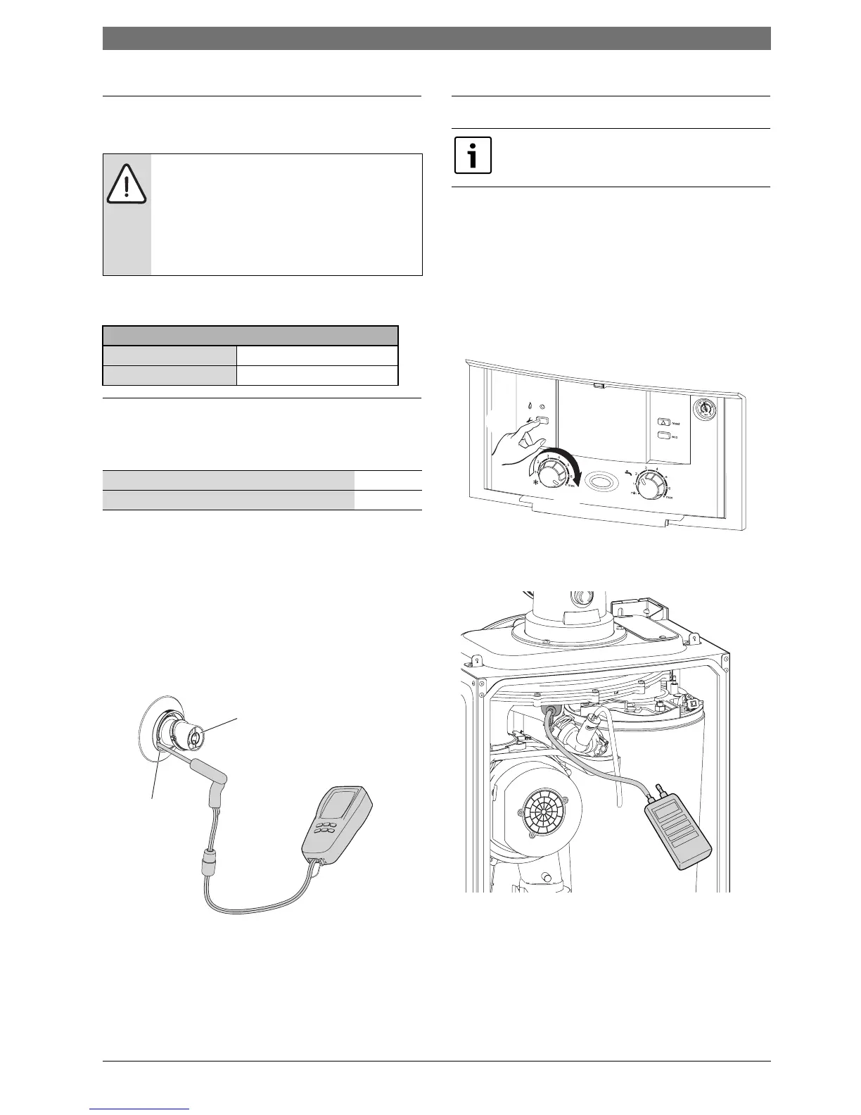
6.4 Fan pressure test
Setting the boiler to maximum
1. Press and hold service button for more than 10
seconds
2. Set the CH temperature to maximum.
– The service button will illuminate continually and
the blue power indicator will pulse 5 times.
– The boiler will stay in this mode for 15 minutes
unless the service button is pressed again.
Fig. 64 Set boiler to maximum
Fan pressure
Fig. 65 Fan pressure test point
B Remove the cover and connect a digital manometer to
the fan pressure test point.
B After measurement replace test point cover.
B The pressure will read negative, refer to the chart in
figure 66.
NOTE:
B Ensure that the gas inlet pressure is
satisfactory with all other gas appliances
working.
B Do not continue with the other checks if
the correct gas inlet pressure can not be
achieved.
Natural gas pressure
at the meter/regulator at the gas control valve
1.13 to 2.75kPa 1.1 kPa min.
Air intake sample point 1
Flue gas sample point 2
Tab. 24 Key to figure 63
6720646195-11.1Wo
1
2
This test is to determine if the heat cell
requires cleaning/attention.
1.
2.
6720643895-106.1Wo
6720643895-58.1Wo
 Loading...