Service and spares | 53AU/NZ
6 720 646 195a (2010/11)
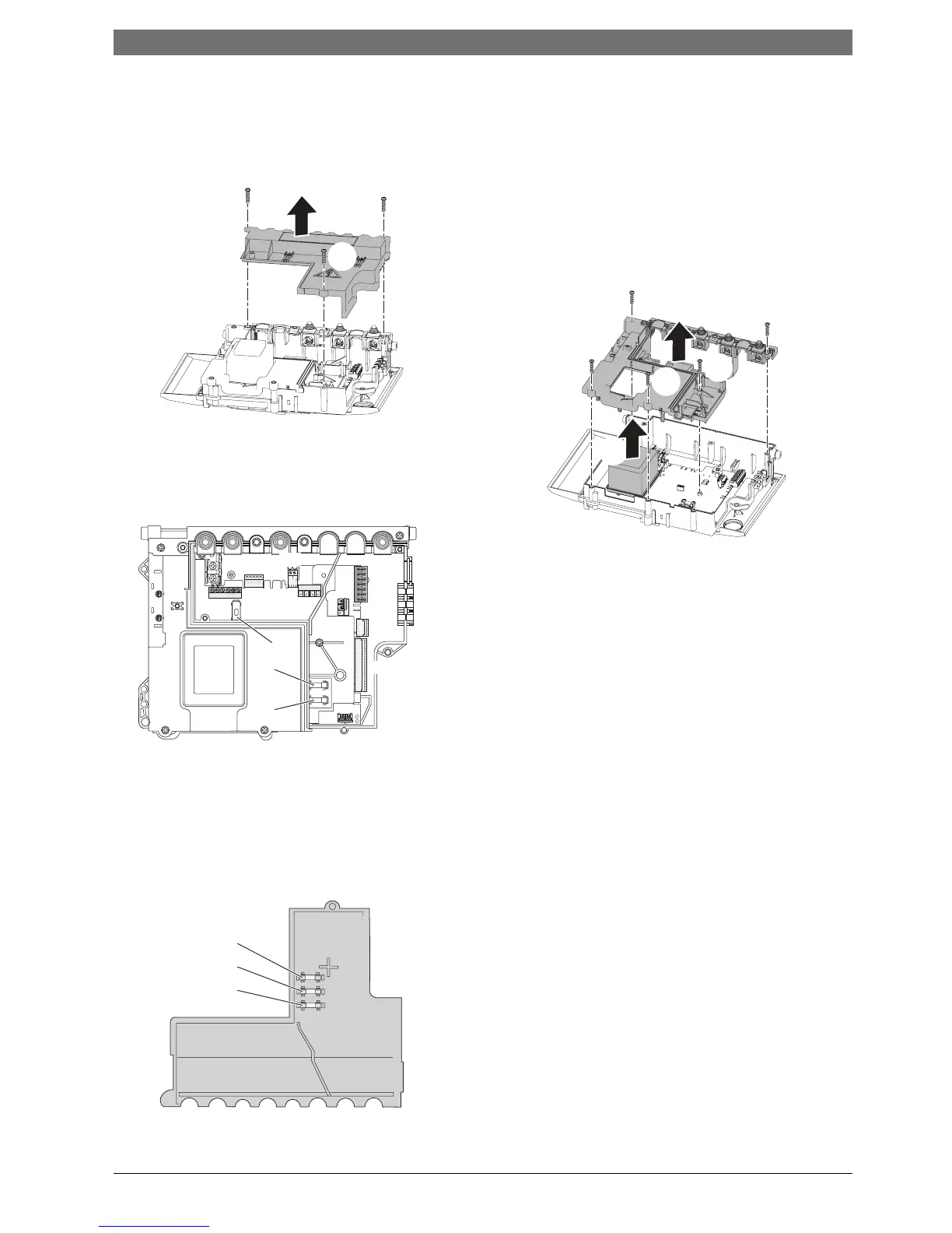
6.8.11 Access to boiler control components
1. Remove three screws.
2. Remove cover from control.
Fig. 95 Removing the connection cover
6.8.12 PCB Fuse
B Remove fuse holder with fuse F1 (1) from the PCB
and replace a new fuse.
Fig. 96 Fuse locations
B Spare fuses are clipped into the underside of the
electrical cover.
1. T1.6L 250V
2. T2.5H 250V
3. T500L 250V
Fig. 97 Spare fuses
6.8.13 Transformer/PCB
Refer to figure 98.
B Disconnect all electrical connections from the
control.
1. Remove five screws retaining the rear panel of the
control.
2. Remove the rear panel.
3. Remove the transformer cover.
Fig. 98 Transformer/PCB access
Refitting the control board cover:
B Ensure that all wires are fully within the control board.
B Align the front right hand corner of the cover with the
front right hand corner of the control board.
B Align the rear right hand .
B Holding the cover level, slide the cover onto the
control board, ensuring that the incoming cables, at
the top, are held clear.
1.
1.
1.
2.
6720643895-40.1Wo
6720643895-74.1Wo
1
2
3
L
N
S
N
L
S LR
FSFR NP LP
B
B
4
2
1
A
F
7
8
9
Code Plug
Fan
Harness
S11
2.5 A 230 V AC
DV
Harness
S13
1.6 A
S12
0.5 A
ST10
ST8
ST6
ST19
Pump
Harness
Main
Harness
6720643895-75.1Wo
3
1
2
1.
1.
1.
3.
6720643895-76.1Wo
2.
1.
1.
 Loading...