EasyManua.ls Logo

Bose 1801 Service Manual

Bose 1801
32 pages
To Next Page IconTo Next Page
Page #1 background imageLoading...
Page #1 background image
Bose
®
Model 1801/1800
Power Amplifier
Supplement
Part Number 192527-S1
©
2001 Bose Corporation
10/2001
SUPPLEMENT
Q4, part number 102428 and Q5, part number 102429 are no longer available with the lead length
needed for soldering to the PCB. Use the part numbers listed below when ordering these transis-
tors. Make a note in your Model 1801/1800 power amplifier service manual, part number 192527.
Reference
Designator
Description Part
Number
Note
Q4 SIM, 2N2219 102428-1K 1
Q5 SIM, 2N5415 102429-1K 2
NOTE: The part numbers listed are kits. They include the following parts:
1. Q4 kit: 1 102428 transistor
3 264371 extension pins
1 192527-S1 supplement.
2. Q5 kit: 1 102429 transistor
3 264371 extension pins
1 192527-S1 supplement.
Question and Answer IconNeed help?

Do you have a question about the Bose 1801 and is the answer not in the manual?

Bose 1801 Specifications

General IconGeneral
Power Output250 watts per channel into 8Ω (stereo)
Frequency Response20Hz to 20kHz
Damping Factor200
Input Sensitivity1.5V
Speaker Load Impedance4Ω to 8Ω
Total Harmonic Distortion0.5%

Summary

SUPPLEMENT

Bose® Model 1801/1800 Power Amplifier

Identifies the main subject of this supplemental document.

Q4 and Q5 Transistor Part Update

Details new part numbers for Q4 and Q5 transistors and their kit contents.

SPECIFICATIONS

Mechanical and Power Details

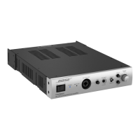
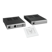
Covers unit dimensions, weight, power requirements, output power, and performance characteristics.

SAFETY INFORMATION

Component Replacement and Electrical Safety Tests

Guidelines for using correct replacement parts and performing essential electrical safety checks.

DEVICE HANDLING AND DESCRIPTION

ESDS Device Handling Precautions

Recommended safety measures for handling Electrostatic Discharge Sensitive devices.

General Unit Overview

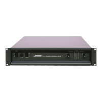
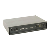
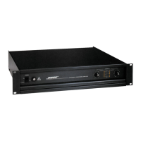
A brief description of the Bose 1800/1801 amplifiers' design and features.

Disassembly and Assembly Procedures

1801 Amplifier Procedures

Step-by-step instructions for disassembling and assembling the 1801 power amplifier.

1800 Amplifier Procedures

Step-by-step instructions for disassembling and assembling the 1800 power amplifier.

Test Procedures

Operational Testing Methods

Procedures for testing bias adjustment, frequency response, DC offset, power output, and distortion.

Part List Notes

Notes on Parts and Ordering

Explanations regarding part availability, special components, and usage notes for the part list.

Part Lists

Main Components and Resistors

Lists of main components and resistors with part numbers and specifications.

Capacitors, Diodes, and Transistors

Lists of capacitors, diodes, and transistors used in the amplifiers with their details.

Troubleshooting Guide

Common Symptoms and Solutions

Identifies common issues like DC offset, high current, oscillation, and their potential causes and solutions.

Voltage Conversion Instructions

Conversion Steps and Wiring Details

Instructions and diagrams for converting the amplifier between 110V and 220V operation.

Service Bulletins

Bulletin #13 - PCB and Transformer Interchangeability

Details interchangeability of PCBs and use of toroidal transformers.

Bulletin #13A - Resistor Failure

Addresses resistor failure and proposes reliability improvement modifications.

Bulletin #17 - Thermal Stability

Outlines methods to improve the thermal stability of the 1800 amplifier.

Bulletin # Pro-81-001 - Output Transistors

Provides information on output transistor changes and compatibility for service.

Related product manuals