Figure 6). The system
i
on the &her. The
ts ~~~~~t~~~ly re
cable jacket with
* Do not connect the powered AcorMimass module directly to your TV unless /he
TV provides surround decoding circuir’vy and amplified o
uts for all channels.
1~ Inserl: -khe ~ul~i-~i~ ~~n~~~~~~ cm %he ~y~~~~ inpu% 6: into the input jack can the ~~Q~~-
ule. ~i~h~~~ the two ~h~~~~~y~w~ to ~~~~~~ a ~~~ur~ ~~~~~~~i~~~
2,
ucxeivcx, ~~~~~ully rnakh “the ~~l~ri~y of %he ~~~~~~~i~~~ (+ to + and -~ to -)”
* ~~~~~h each ~~~~~~ wire (+) ts “dhe ~~~~~~ri~~~ t- ~~~~~~~~~
a The RCA plug of the system inpuf cable comes wifh a couer installed. Remove this
cove; for connection to the LFEXYJB!NOBFER OUTjack. If your receiver has no LFE/SUB-
WOOFER OIJTjack, leave Che plug cover in place.
3.
CA plug cm the ~y~~~~ inpud ca
FE
UT jack m your ~~r~~~tl~ rxxx%vfx
a Do not allovv exposed wires ii? brush against each other; this could damage your
receivet:
Connecting
the
Acoustimass@
module
to
the
receiver
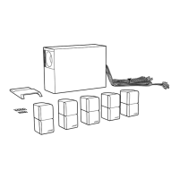
The 20-foot
(6.1
m)
system input cable connects the module
to
your surround receiver (see
Figure
6).
The system input cable has a multi-pin connector on one end and several wire pairs
on the other. The wire pairs
of
the cable may be separated or "unzipped" as much as needed
to
comfortably reach the surround receiver connections. Each wire pair is marked on the
cable jacket with RIGHT, LEfT, CENTER, RIGHT SURROUND or
LEfT
SURROUND
to
indi-
cate where each wire connects
to
the receiver.
A CAUTHON: Before making
any
connections
tum
off
your
receiver
and
unplug
it from the
AC
(mains) outlet.
Not
doing
so
may
result in
damage
to
your
system.
A CAUTHON: Do
not
connect
the
powered
Acoustimass module directly to
your
TV
unless the
TV
provides surround
decoding
circuitry
and
amplified
outputs for all channels.
1.
Insert the multi-pin connector on the system input cable into the input jack on the Acous-
timass module. Tighten the
two
thumbscrews
to
assure a secure connection.
2.
Connect each wire pair on the other end
of
the system input cable to your surround
receiver. Carefully match the polarity
of
the connections
(+
to + and
-.
to
-).
o Attach each marked wire
(+)
to
the appropriate + terminal.
o Attach each plain wire H to the appropriate
~
terminal.
j N@te:
The
RCA
plug
of
the system
input
cable
comes with a
cover
installed. Remove this
cover
for connection to the LFE/SUBWOOFER
OUTjack.
If
your
receiver has no LFE/SUB-
WOOFER
OUT
jack, leave the
plug
cover
in place.
S.
If applicable, connect the RCA plug on the system input cable
to
the LFE/SUBWOOFER
OUT jack on your surround receiver.
A
CAUTION:
Do
not
allow
exposed
wires to brush against
each
other; this Gould
damage
your
receiver
10
 Loading...