34
DISASSEMBLY PROCEDURES
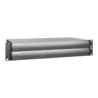
3.4 Remove the twelve screws that secure
the XLR jacks to the back of the chassis.
Remove the one screw that secures the
USB connector to the chassis.
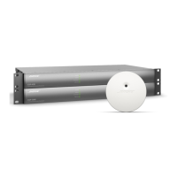
3.5 Remove the two screws (4) that secure
the Input / Output PCB (2) to the chassis.
3.6 Slide the I/O PCB toward the front of the
chassis and lift it out.
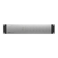
4. Switch-Mode Power Supply PCB
Removal
4.1 Perform procedure 1.
4.2 Unplug the cable harnesses from the AC
line input at XS1, from the DSP PCB at XS4
and the Input/Output PCB at XS5.
4.3 Unplug the wire harness that runs from
the Button/LED PCB at XS3 and the AC
Power Switch PCB at XS2.
4.4 Remove the four screws that secure the
switch-mode power supply PCB to the
chassis. Lift out the PCB assembly.
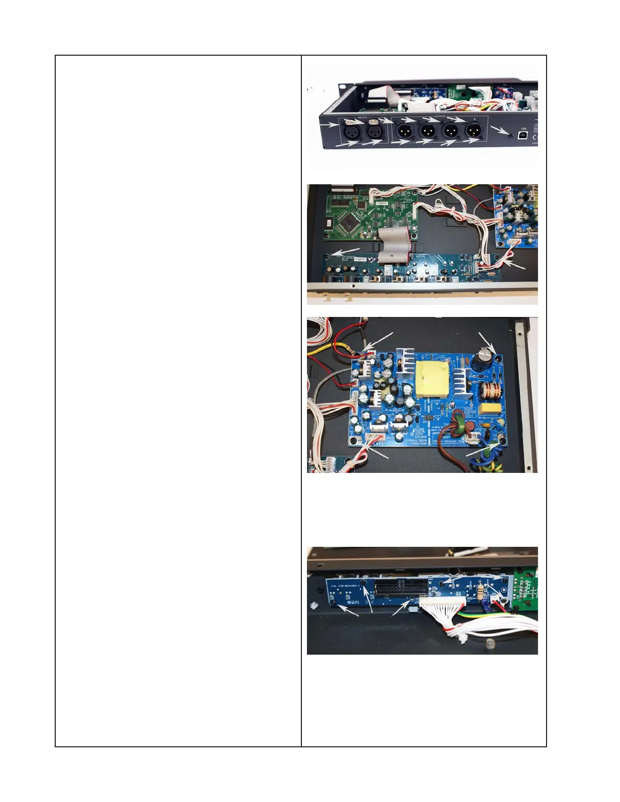
5. Button/LED PCB Removal
5.1 Perform procedure 1.
5.2 Unplug the ribbon cable from J302.
Unplug the ribbon cable from J303. Unplug
the wire harness from the switch-mode
power supply at XS3.
5.3 Using a right-angle Phillips-head screw-
driver, remove the six screws that
secure the PCB to the front panel.
5.4 Slide the PCB toward the rear of the
chassis and lift it out.

 Loading...