35
DISASSEMBLY PROCEDURES
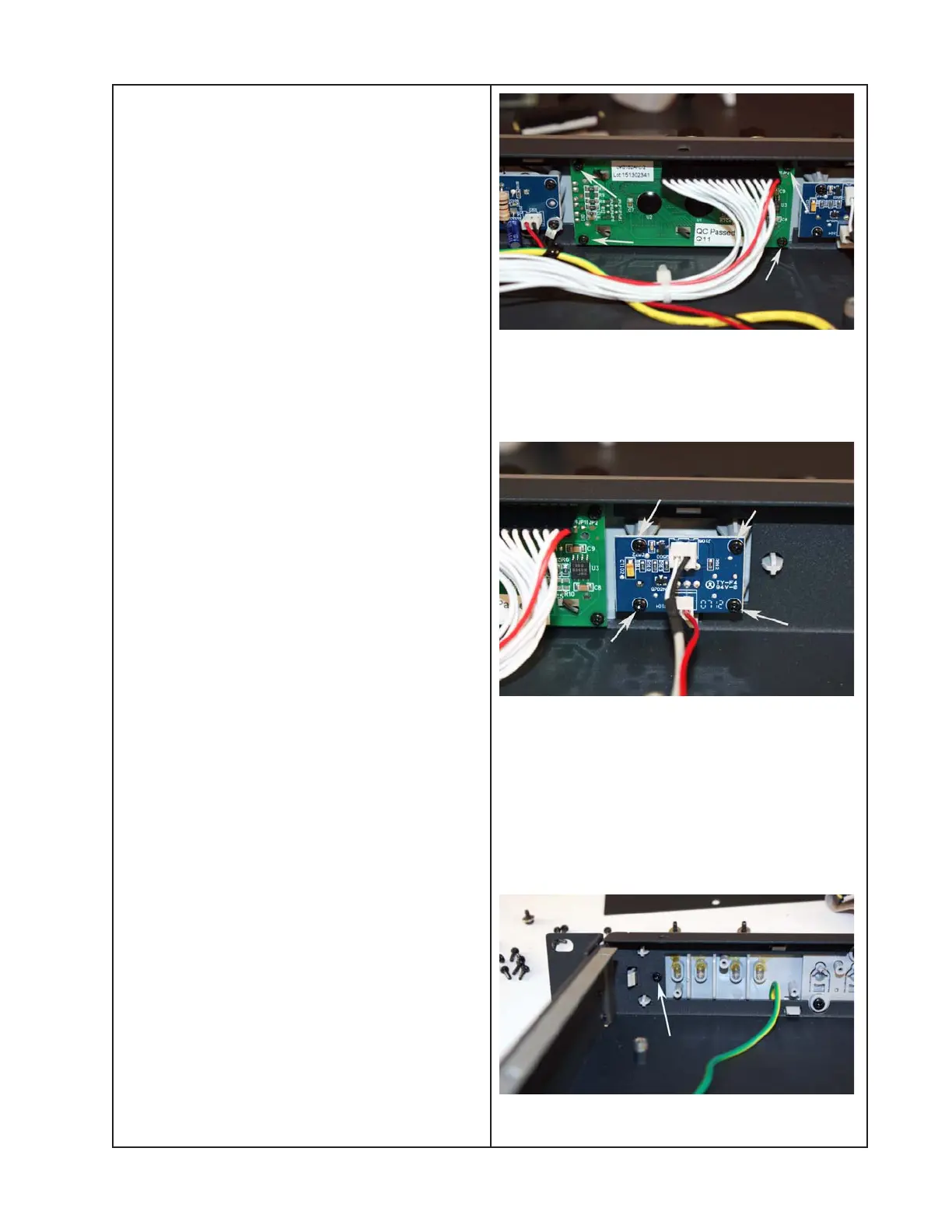
6. Display PCB Removal
6.1 Perform procedure 1.
6.2 Unplug the Display PCB’s ribbon cable
from the Button/LED PCB at J303.
6.3 Using a right-angle Phillips-head screw-
driver, remove the four screws that secure
the Display PCB to the plastic front panel.
6.4 Lift out the Display PCB.
Re-assembly Note: Be sure to properly
align the Display PCB with the front panel
when re-installing it. The ribbon cable should
be located near the top of the front panel.
7. Power Switch PCB Removal
7.1 Perform procedure 1.
7.2 Unplug the Power Switch PCB (17) wire
harness from the switch-mode power supply
PCB at XS2.
7.3 Remove the four screws that secure the
PCB to the plastic front panel. Lift out the
PCB.
7.4 Pull the ON/OFF power button off of the
power switch SW106. You will need to re-
use this button with the new switch.
Re-assembly Note: Attach the power ON/
OFF button to the new switch using a small
amount of general purpose adhesive ap-
proved for use on plastic. Be sure that the
vertical line on the power button faces
toward the top of the front panel.
8. Front Panel Removal
8.1 Perform procedures 5, 6 and 7 to remove
the Button/LED PCB, Display PCB and the
Power Switch PCB.
8.2 Remove the two screws that secure the
plastic front panel to the metal chassis.
There is one screw at each end of the
chassis. The photo at right shows one of
these two.

 Loading...