40
Hi-Pot tester settings:
IMPORTANT:
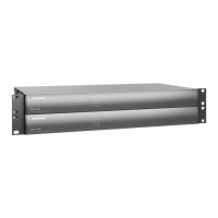
The SP-24 Sound Processor needs to be
tested using two different settings as shown
below. Two different connection points are
used for these tests. Be sure to use the
correct voltage setttings for each connection
point.
14.4 Perform the Hi-Pot test at the chassis
connection point. Be sure that the unit is fully
re-assembled with the exception of the top
cover.
- When connected to the chassis, use the
following settings.
2.120 KVDC / High .5 ma / Low 0 ma /
Ramp 1 Sec. / Dwell 1 Sec. / Continuity
OFF
14.5 Once the UUT has passed the Hi-Pot
test at this settings level, replace the top
cover, ensuring that there are no pinched
wires between the cover and the unit.
14.6 Connect an XLR test cable to one of the
channel 1 - 4 output jacks. This test cable
should have only the ground (pin x) connec-
tion at the XLR end and an RCA connector at
the other end. This adapter cable would
connect to the RCA test cables supplied with
the tester.
14.7 Be sure that the unit is fully re-as-
sembled for this test, including the top cover.
- Perform the Hi-Pot test at an XLR output
connector using the below settings.
3.540 KVDC / High .5 ma / Low 0 ma /
Ramp 1 Sec. / Dwell 1 Sec. / Continuity
OFF
14.8 If the unit passes testing at both voltage
levels, it can be returned to the customer.
If the unit fails this test, it must be returned
to the repair tech for troubleshooting and
repair and then be retested.
TEST PROCEDURES
If the ground connection from the AC inlet to
the chassis needed to be disconnected as
part of the repair, then the unit would also
need the Ground Bond test below.
15. Ground Bond Test
IMPORTANT:
This test MUST be performed if the ground
connection from the AC inlet to the chassis
has been disturbed as part of a repair. This
test ensures that the ground connection can
take the full current of the AC line if needed
due to a product failure.
It does this by measuring the current han-
dling capability of the ground connection by
putting a high current through the ground
blade of the AC line cord and measuring the
leakage current on the exposed metal part
of the chassis.
15.1 Plug the AC line cord into the AC
adapter box supplied with the Hi-Pot tester.
Connect the return line from the Hi-Pot tester
to an exposed metal section of the chassis.
Ensure a good electrical connection.
15.2 Perform the ground bond test in accor-
dance with the parameters below.
- 10Amps, < 12VAC open circuit,
< 0.1 Ohms.
15.3 If the unit passes this test and the Hi-
Pot tests, it can be returned to the customer.
If the unit fails this test, it must be returned
to the repair tech for troubleshooting and
repair and then be retested.

 Loading...