39
TEST PROCEDURES
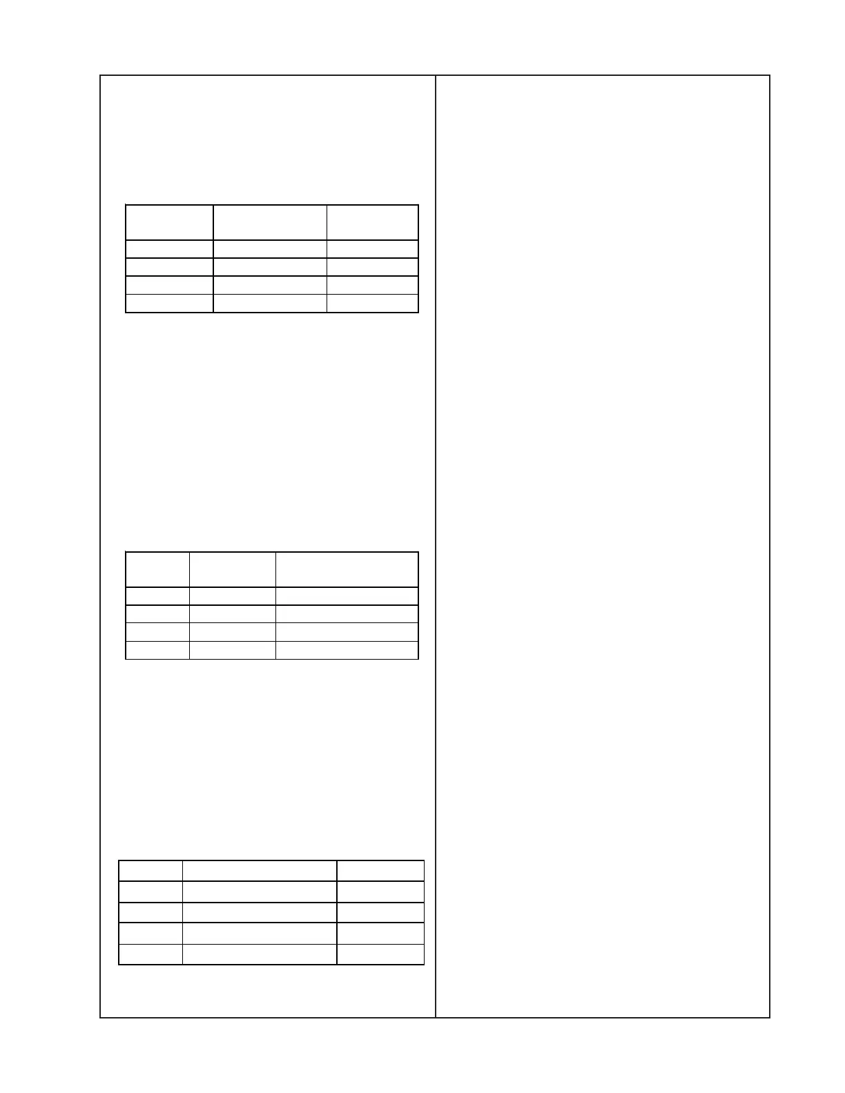
10. Crosstalk Test
10.1 Apply a 1 kHz, 0 dBu sine wave into
input A or B only. Using a 1 kHz band reject
filter, measure the signal level in dB at the
outputs specified below.
11. Output Noise Test
11.1 Configure as follows:
All inputs terminated 600 ohms each leg to
GND and undriven. All outputs terminated
600 ohms, each leg to ground.
11.2 Measure the output noise level at each
of the output 1 - 4 XLR connectors. Ensure
that the noise levels are in accordance with
the below table.
12. Maximum Input Signal Test
12.1 Configure as follows:
Input sensitivity at +18 dBu.
12.2 Apply a 1 kHz, +19 dBu sine wave to
Inputs A and B. Measure the output 1 - 4
THD+N levels and ensure that they are in
accordance with the below table.
Input
Channel
Measurement
Channel
Output
Level
A 2 < -90 dB
B 1 < -90 dB
A 4 < -90 dB
B 3 < -90 dB
Output Connecto
Noise(20Hz
22KHz), Un-Wtd
1 XLR 1, < 20 µV
2 XLR 2, < 20
V
3 XLR 3, < 20 µV
4 XLR 4, < 20 µV
13. Turn-off Pop Test
13.1 Turn the unit OFF by pressing the
power switch on the front panel. Verify that
there is no audible off-pop when connected
to an amplifier with 36dBG and a loud-
speaker.
14. Hi-Pot Test
WARNING
This test is REQUIRED on all units that
have been repaired after they have been
fully reassembled.
This is a safety test designed to ensure that
the product is safe to return to the customer
after a repair. It tests leakage current to the
chassis and exposed metal parts by apply-
ing a high voltage level across both pins of
the AC line cord at the same time and mea-
suring the leakage current.
This test captures reassembly errors
(pinched wires) as well as testing the wiring
insulation and the primary side of the power
supply.
14.1 The power switch on the front panel
must be in the ON position for this test.
Press the switch to the ON position.
14.2 Test is to be performed from the AC
input to the exposed earth (GND) parts of
the chassis.
14.3 With the top cover ONLY removed,
connect a test lead with an alligator clip to
the bare metal edge of the top of the
chassis. This lead would connect to the
return connection on the Hi-Pot tester. The
AC line cord would connect to the back of
the UUT and to the AC adapter test box
for the Hi-Pot tester.
Outpu
Level THD + N
1 +19.6 dBu +/- 0.5 dB < 0.1%
2 +19.6 dBu +/- 0.5 dB < 0.1%
3 +19.6 dBu +/- 0.5 dB < 0.1%
4 +19.6 dBu +/- 0.5 dB < 0.1%

 Loading...