7 of 36
2.0 Hardware Description
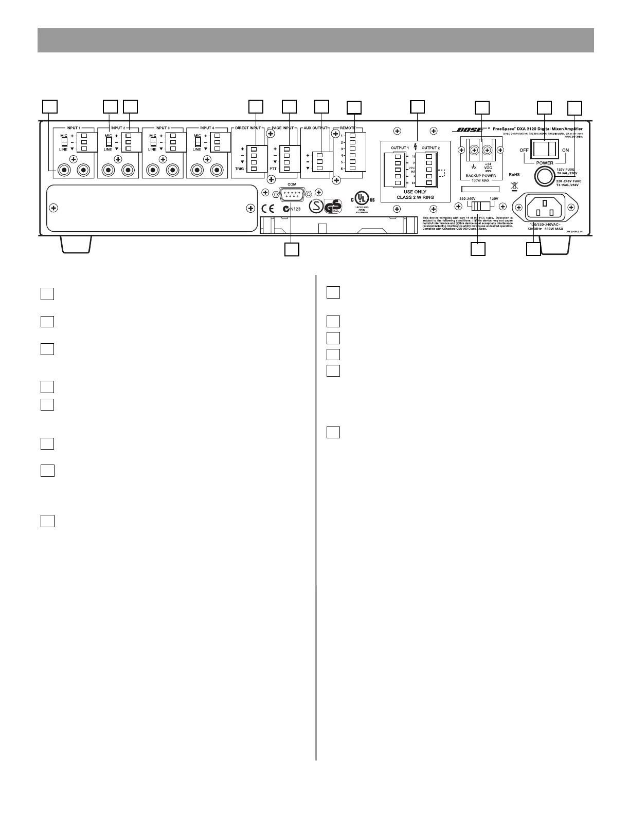
2.3 Rear panel
1
3
2
4
5
8
7
9 10
12
13
14
11
6
2.3.1 Audio source inputs
1 LINE INPUTS – Two unbalanced RCA audio jacks per input
(summed to mono).
2 MIC/LINE INPUTS – Balanced Euroblock input jacks. One
per inp
ut.
3 MIC/LINE switch – Adjusts for the proper signal level being
used with the four Euroblock input connectors.
(Mic connections require using the Euroblock input jacks.)
4 DIRECT INPUT –
Balanced override input jack.
5PAG
E INPUT – Balanced audi
o input jack.
2.3.2 Outputs
6 AUX OUTPUT – Line-level signal output for other amplified
e
quipment.
7OUTPUTS 1 and 2 – Speaker connections for two powered
outputs (70V, 100V, or 4 ohms operation).
2.3.3 Control input
8 REMOTE – Input jack for volume-only control and volume
con
trol with A/B select user interfaces.
2.3.4 Power
9 BACKUP POWER – For connection to backup power
source.
10 POWER OFF/ON – AC power switch.
11 FUSE – 120V T6
.3AL/250V or 220-240V T3.15AL/250V.
12 AC mains line cord jack –
AC line voltage input.
13 120V/220
-240V switch – Switches between 120
V and
220-240V AC input voltage. This switch is not pr
ovided on
100V AC
input voltage models.
2.3.5 Communication
14 COM – RS-232 serial port is reserved for system updates.
2.0 Hardware Description.fm Page 7 Monday, February 12, 2007 8:51 AM
 Loading...


