23 of 76
3.0 E-4 Hardware Description
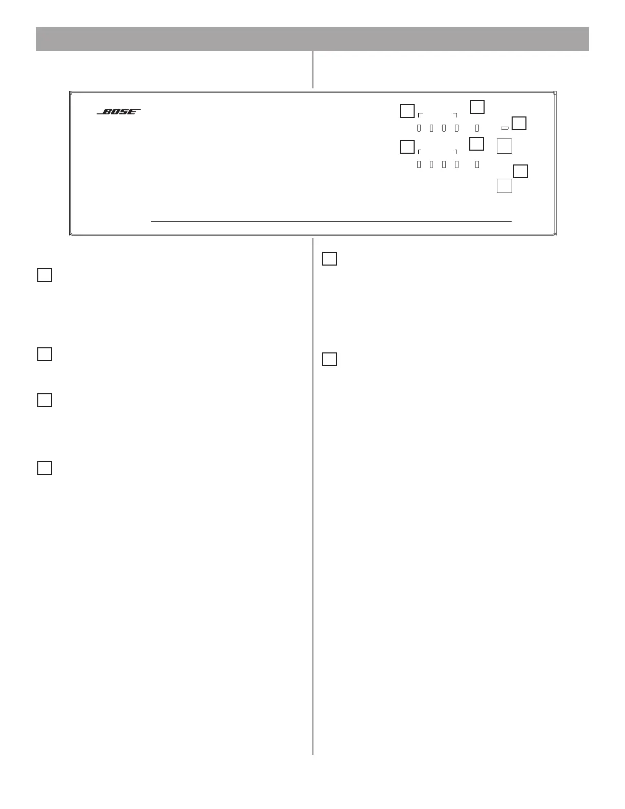
3.1 Front panel
3.1.1 Controls
STANDBY – The STANDBY button switches the unit
between standby and active. The color of the LED above the
switch indicates the status:
Amber = Unit is in standby
Unlit = Unit is active
USB – A USB communications port (for future use)
3.1.2 Indicators
SYSTEM STATUS – The SYSTEM STATUS LED indicates
the condition of the unit:
Green = Normal operation
Red = Fault condition
AMP OUTPUTS – These LEDs work in pairs (1 and 2, 3 and
4) and indicate the operating status of the four amplifier output
channels:
Green = Normal operation
Red = Fault condition
Unlit = No signal
AUDIO SOURCES – These LEDs indicate the operating
status of the four input sources:
Green = Good signal
Amber = Low signal
Red = Signal clipping
Unlit = No signal
DIRECT INPUT – The color of this LED indicates the condi-
tion of the source connected to the DIRECT IN/CONTROL con-
nector on the rear panel.
Amber = Active bypass
Unlit = Normal operation
DIRECT
INPUT
USB
AUDIO SOURCES
14
23
STANDBY
FreeSpace
Business Music System
SYSTEM
STATUS
AMP OUTPUTS
14
23
1
2
3
4
5
6
1
2
3
4
5
6