34 of 76
5.0 Using FreeSpace
®
System Installer™ Software
5.1 Installing the software
Insert the FreeSpace system Installer™ software CD into the CD
tray of your laptop PC.
If the install program does not start automatically, open “My
computer” from the desktop, double-click on the CD-ROM drive
icon, and double-click on the “Setup.exe” icon.
Follow the instructions on the screen to complete the installation.
Programmer’s Note: For the Installer™ software to
operate properly, your PC must be connected to the E-4
hardware. See the following section, “Connecting to the
E-4 system”.
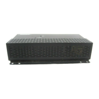
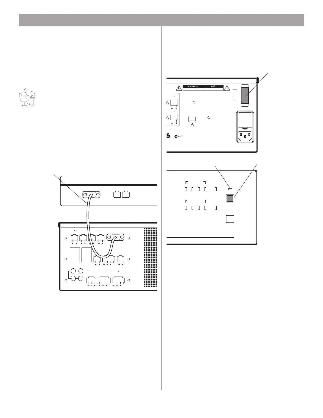
5.2 Connecting to the E-4 system
Before you can configure a hardware device, your PC must first
be physically connected to the hardware device with a serial
cable and then that connection must be activated using the soft
-
ware.
1. Connect the RS-232 serial port of your laptop PC to the
RS-232 serial port on the rear panel of the E-4 hardware.
2. Set the rear panel POWER switch to ON. Verify that the
STANDBY indicator is lit on the E-4 front panel. Then press
the STANDBY push button to switch the E-4 hardware to the
operating mode.
ZONE4
LINE OUT
DIRECT IN/
CONTROL
SENSE MICROPHONES
ZONE 1 ZONE 2 ZONE 3 ZONE 4
WALL PLATE CONNECTIONS
REMOTE
ON/OFF
LINE 2
MUSIC ON
HOLD/
PBX OUT
RS232
AUX MIC/
LINE 3
PAGE/ MIC/
LINE4
1
3
2
4
LINE 1
AUDIO SOURCES
PTT PTT
12V
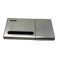
RS232
Laptop PC
RS-232 serial data cable
(not provided)
E-4 system
DIRECT
INPUT
USB
AUDIO SOURCES
14
23
STANDBY
SYSTEM
STATUS
AMP OUTPUTS
1423
OUT
Bose Corporation, Framingham, MA 01701-9168
Made in the U.S.A.
70V 100V
RISQUE DE CHOC ELECTRIQUE
NE PAS OUVRIR
RISK OF ELECTRICAL SHOCK
DO NOT OPEN
POWER
ON
OFF
OUTPUT
VOLTAGE
4
2
DO NOT SWITCH
WHILE POWER IS ON
FreeSpace Model E-4
400 Watt System Electronics
IRING
OUT
100/120V~AC T6.25A, L250V
220/240V~AC T3.15A, L250V
50/60Hz
300W MAX
geprüfte
Sicherheit
CC rules. Operation is
device may not cause
accept any interference
use undesired operation.
pec.
POWER switch
STANDBY indicator
STANDBY push button