29 of 76
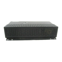
4.0 Hardware Installation
4.7 System wiring
Installer’s Note: Disconnect the E-4 unit from the AC
(mains) power before making any input/output connections.
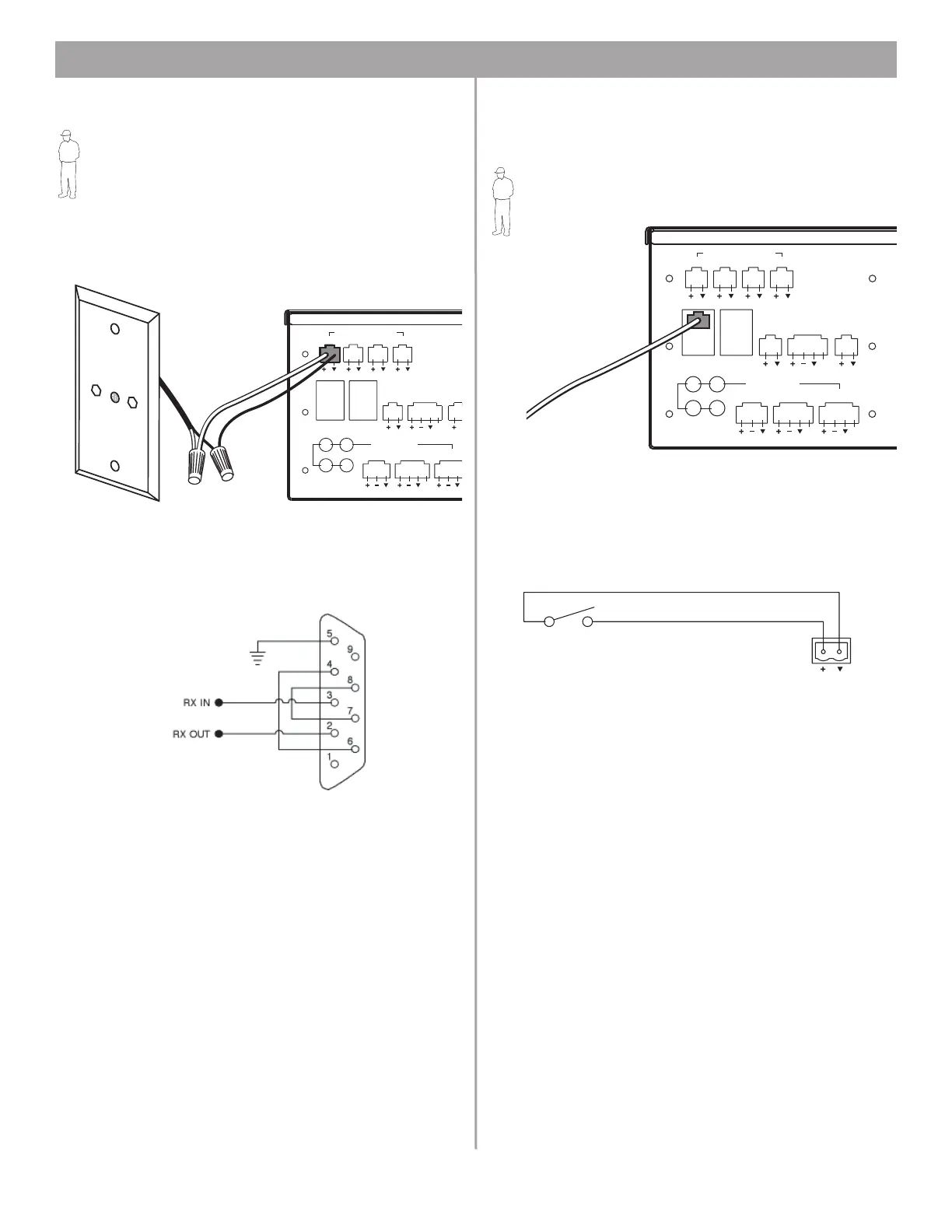
4.7.1 Auto volume microphone inputs
Connect each sensing microphone to the SENSE MICRO-
PHONES jacks on the E-4 rear panel.
4.7.2 Serial data communications
Connect your PC to the E-4 unit using a straight-wired serial data
cable (DB9 male to DB9 female).
4.7.3 User interface connections
Connect the user interface from each zone to the appropriate
WALL PLATE CONNECTION jack.
Installer’s Note: Only use standard ethernet (Cat 5) cable
to connect the user interface to the E-4 unit. DO NOT use
crossover (XOV) cables.
4.7.4 Remote standby switch
If you are installing a remote standby switch, connect it to the
REMOTE ON/OFF input.
ZONE4
LINE OUT
DIRECT I
CONTRO
SENSE MICROPHONES
ZONE 1 ZONE 2 ZONE 3 ZONE 4
WALL PLATE CONNECTIONS
REMOTE
ON/OFF
LINE 2
MUSI
HOL
PBX
RS232
AUX MIC/
LINE 3
PAGE/ MIC/
LINE4
1
3
2
4
LINE 1
AUDIO SOURCES
PTT
12V
RS232 port pinout
ZONE4
LINE OUT
DIRECT IN/
CONTROL
SENSE MICROPHONES
ZONE 1 ZONE 2 ZONE 3 ZONE 4
WALL PLATE CONNECTIONS
REMOTE
ON/OFF
LINE 2
MUSIC ON
HOLD/
PBX OUT
RS232
AUX MIC/
LINE 3
PAGE/ MIC/
LINE4
1
3
2
4
LINE 1
AUDIO SOURCES
PTT PTT
12V
Remote Standby
Switch
E-4
REMOTE ON/OFF
Normally Open
Switch (latching)