28 of 76
4.0 Hardware Installation
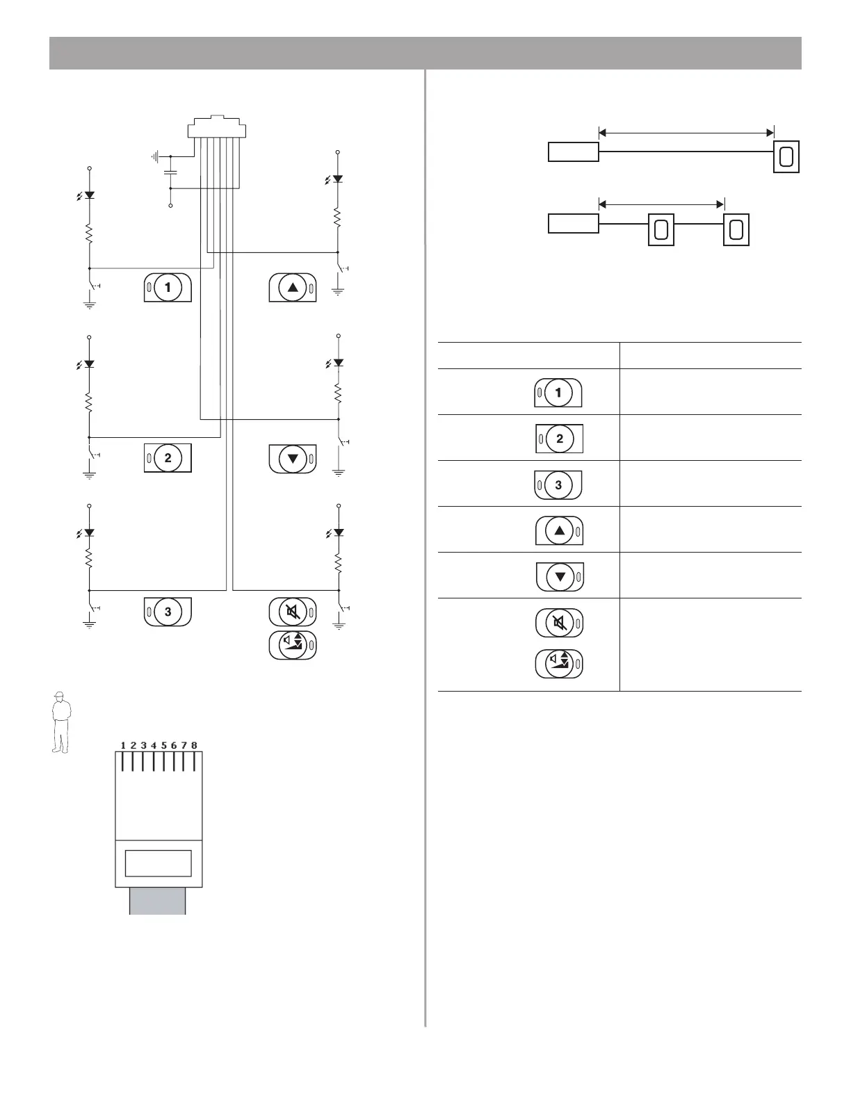
Keypad schematic:
User interface wiring:
Installer’s Note: Use only standard ethernet (Cat 5) cable
to connect the user interface to the E-4 unit. DO NOT use
crossover (XOV) cables.
Recommended cable lengths:
Disabling keypad keys:
If you do not want a particular keypad function to operate in a
zone, you can disable the key by modifying the wiring of the
ethernet cable.
For operation information, see “User Interface Operation” on
page 60.
S1
Source 1
+5VD
D1
LED
R1
562
S6
Volume Up
+5VD
D6
LED
R6
562
JR1RJ-45
1 2 3 4 5 6 7 8
.33µF
C7
+5VD
S5
Volume Down
+5VD
D5
LED
R5
562
S2
Source 2
+5VD
D2
LED
R2
562
S4
Mute
or
Auto Volume
On/off
+5VD
D4
LED
R4
562
S3
Source 3
+5VD
D3
LED
R3
562
RJ45
568A Color Code
1 – White/Orange
2 – Orange
3 – White/Green
4 – Blue
5 – White/Blue
6 – Green
7 – White/Brown
8 – Brown
To disable this key: Make no connection at pin:
Source 1 4
Source 2 5
Source 3 6
Volume
Up
3
Volume
Down
2
Mute
or
Auto
Volume
On/Off
7
E-4
2000 ft (610 m) max.
E-4
1300 ft (396 m) max.
One wall plate
using CAT 5
Two wall plates
using CAT 5