45 of 76
6.0 E-4 System Setup
6.1 Introduction
This section provides instructions on setting up an installed E-4
system. To set up an E-4 system you need a PC running the
FreeSpace
®
system Installer™ software.
6.2 Connecting your PC to an
E-4 system
Before you can set up the E-4 system, your PC must first be
physically connected to the E-4 unit with a serial cable and then
that connection must be activated using the
Installer™ software.
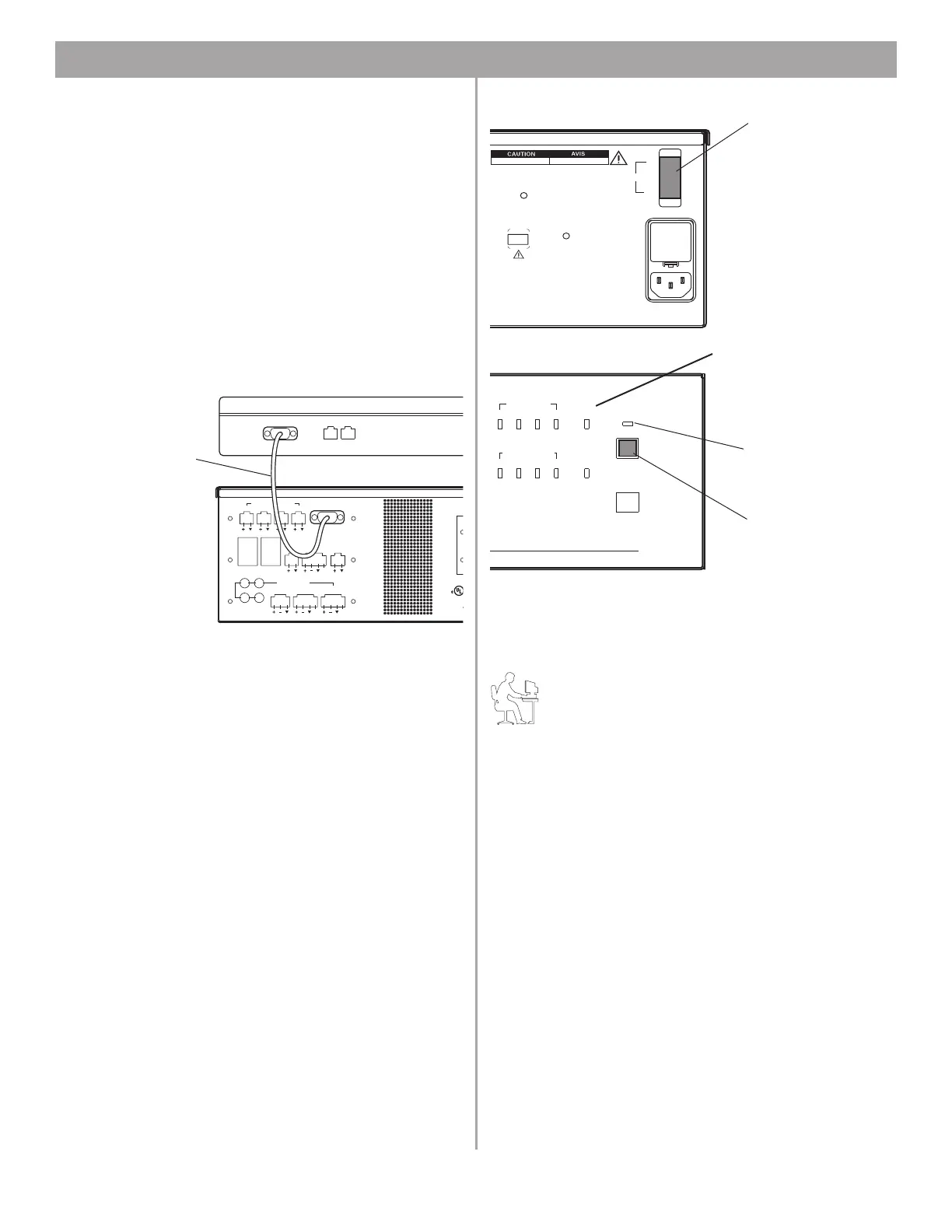
1. Connect the RS-232 serial port of your PC to the RS-232
serial port on the rear panel of the E-4 unit using a straight
serial data cable.
2. Set the E-4 rear panel POWER switch to ON. When the E-4
unit is powered up and ready, the SYSTEM STATUS indica
-
tor is dark (unlit) and the STANDBY indicator is amber.
3. Press the STANDBY push button to switch the E-4 hardware
to the operating mode. The STANDBY indicator will turn off
and the SYSTEM STATUS indicator will be green. (If a sys
-
tem fault condition exists, the indicator will be red.)
Programmer’s Note: If the E-4 system experiences a
brownout or power loss, the E-4 hardware will return to
power in the STANDBY mode. To return to operation,
press the STANDBY button, or press any key on any
user Interface.
4. Launch the Installer™ software. See “Using FreeSpace
®
System Installer™ Software” on page 34 for more informa-
tion on the launching sequence.
ZONE4
LINE OUT
DIRECT IN/
CONTROL
SENSE MICROPHONES
ZONE 1 ZONE 2 ZONE 3 ZONE 4
WALL PLATE CONNECTIONS
REMOTE
ON/OFF
LINE 2
MUSIC ON
HOLD/
PBX OUT
RS232
AUX MIC/
LINE 3
PAGE/ MIC/
LINE4
1
3
2
4
LINE 1
AUDIO SOURCES
AUDIO
EQUIPMEN
LISTED 917
®
PTT PTT
12V
This dev
subject t
harmful i
received,
Complie
C
O
RS232
Laptop PC
RS-232 straight
serial data cable
(not provided)
E-4 system
DIRECT
INPUT
USB
AUDIO SOURCES
14
23
STANDBY
SYSTEM
STATUS
AMP OUTPUTS
1423
Bose Corporation, Framingham, MA 01701-9168
Made in the U.S.A.
70V 100V
RISQUE DE CHOC ELECTRIQUE
NE PAS OUVRIR
RISK OF ELECTRICAL SHOCK
DO NOT OPEN
POWER
ON
OFF
OUTPUT
VOLTAGE
DO NOT SWITCH
HILE POWER IS ON
FreeSpace Model E-4
400 Watt System Electronics
100/120V~AC T6.25A, L250V
220/240V~AC T3.15A, L250V
50/60Hz
300W MAX
s
e
e
.
POWER switch
STANDBY indicator
Amber = Standby
Off = Operating
STANDBY
push button
SYSTEM STATUS indicator
Green = Operating
Red = Fault
Front
Rear