5
PRODUCT DESCRIPTION
12 34
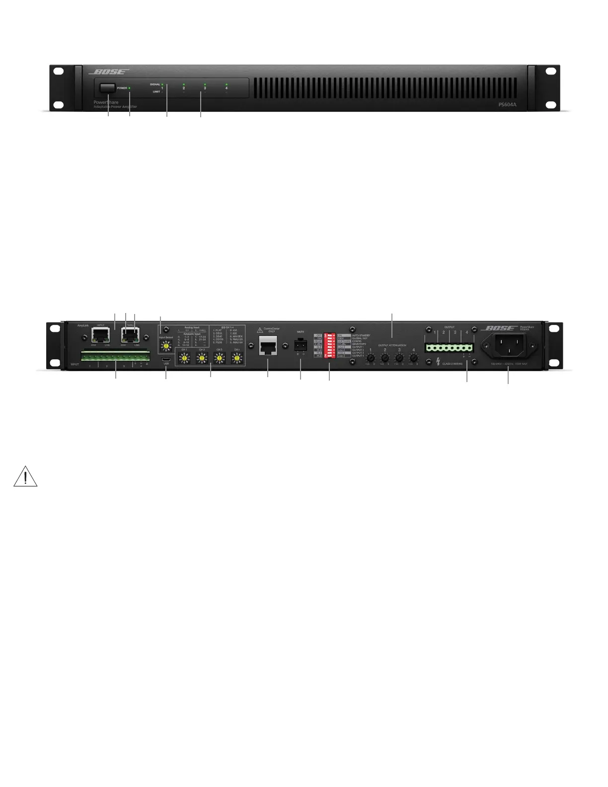
2 AmpLink ERR LED – Solid yellow indicates muted audio from
the mute connector. Blinking yellow indicates an error, which
will also mute the audio.
3 AmpLink LNK LED – Solid green indicates normal operation
4 ANALOG INPUTS – Balanced 12-pin Euroblock line-level input
connector.
5 INPUT SELECT – Dial selects if analog or AmpLink audio
inputs are used. The default state is analog 1:1.
6
MICRO-USB – Connect the amplifier to a PC using a USB
connection. This allows you to use the PC-based PowerShare
Editor software to configure the advanced features of the
amplifier.
7
CHANNEL 1, 2, 3, 4 EQ – Each dial provides loudspeaker
equalization presets per channel: DS 16, DS 40, DS 100,
FS3B, 402, 802, MA12EX, RMU105, and RMU108. Use the Flat
setting for FS3 Omni Systems.
1
POWER SSWW IITTCCHH – ON/OFF AC power.
2
POOWW EERR LED
•Solid green LED indicates the unit is ON.
•Blinking green LED indicates the unit is in low-power mode.
•Solid amber LED indicates an over-temperature fault.
•Solid red LED indicates a power supply fault.
3
INPUT 1, 2, 3, 4 SIGNAL LED – Each LED operates
independently.
•Green LED indicates signal is present.
• Amber LED indicates signal is near clipping.
•Red LED inciates clipping.
•LEDs will display solid red if a power supply fault
is detected.
4
OUTPUT 1, 2, 3, 4 LIMIT LED – Each LED operates
independently.
• LED is amber when the amplifier is limiting the
corresponding output due to exceeding the specified
loudspeaker Vpeak or Vrms limits.
• If the sum of the amplifier outputs exceeds 600 watts, then
the amplifier will limit all outputs equally, and all LEDs will
show limiting simultaneously.
•LEDs will display solid red if an amplifier, power supply, or
EHF fault is detected.
•LEDs will blink red when all outputs are muted.
8
CONTROLCENTER – RJ-45 input connector for Bose CC-1
ControlCenter zone controllers or CV41 4-to-1 converter only.
9
MUTE – Contact closure connection where a short across the
mute connector will mute all outputs. Mute polarity can be
inverted with the PowerShare Editor software.
10
DIP SWITCHES – A bank of switches used to set amplifier
configuration.
11
OUTPUT ATTENUATION 1, 2, 3, 4 – Output attenuators
for each output. Turn the controls clockwise to decrease
attenuation and counter-clockwise to increase attenuation.
12
OUTPUT – Inverted 8-pin Euroblock connector for
loudspeaker connections. Each channel can deliver up to 600
watts regardless of load into 4 Ω, 8 Ω, 70V, or 100V. Outputs
are not bridgeable.
13
AC INNLLEETT
– Removing the AC cord when the amplifier is on
is equivalent to powering down using the front panel power
switch, and is an acceptable power-down method.
23
4
5
7 8 96
1
11
10 12 13
1
AmpLink – INPUT RJ-45 connector that receives up to 24
digital channels from a Bose AmpLink product. The amp also
supports a THRU path for daisy-chaining all 24 digital audio
channels to other Bose AmpLink products, at a maximum
distance of 10 m between products.
CAUTION: Shielded EIA/TIA 568B straight CAT-5 cable, or
eq uivalent, is required for proper AmpLink operation. Unshielded
cable is not supported and may cause AmpLink audio to operate
improperly. Do not connect either of these RJ-45s to a network .