83
TEST PROCEDURE
PS404A and PS604A (AmpLink Version) Amplier Tests
Analog Input Tests
Required Items:
• Audio Precision ATS-1 or equivalent
• Audio Precision AUX-0025 digital lter or similar
• 4 - 4 Ohm, 250W load resistors
• 4 - 16 Ohm, 250W load resistors
• 4 - 32 Ohm, 250W load resistors
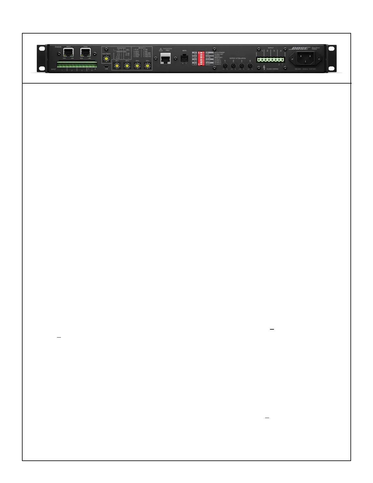
UUT Switch Settings:
Set the PS404A or PS604A rear panel controls as listed below for following tests.
• Analog Input Select Rotary Switch to position 1, 1:1
• Rotary EQ switches to position 1 FLAT
• Output Trims 1 - 4 to MAX (fully CW)
• DIP switch setting: all switches to LEFT
Important Note: All measurements for the power amp require an Audio Precision AUX-0025 Digital
Filter (or equivalent) with a 20Hz-20kHz lter in order to get the correct output noise and level readings.
1. Gain Test - Low-Z Mode
1.1 Set the Output 1 - 4 DIP switches to Low-Z mode (right).
1.2 Connect 4 Ohm, 250W loads to the channel 1 - 4 outputs.
1.3 Apply a 1 kHz, -19.3 dBV input to the channel 1 - 4 inputs.
1.4 Measure the output level at the channel 1 - 4 outputs. It should be +11.2 dBV+1 dBV (PS404A) or
+13 dBV+1 dBV (PS604A).
2. Gain Test - Hi-Z 70V Mode
2.1 Set the Output 1 - 4 DIP switches to Hi-Z mode (left). Set the GLOBAL OUT DIP switch to 70V (left).
2.2 Connect 16 Ohm, 250W loads to the channel 1 - 4 outputs.
2.3 Apply a 1 kHz, -19.3 dBV input to the channel 1 - 4 RCA inputs.
2.4 Measure the output level at the channel 1 - 4 outputs. It should be +16 dBV+1 dBV.
3. Gain Test - Input Sensitivity, 100V and 70V Settings
3.1 Set the Output 1 - 4 DIP switches to Hi-Z mode (left). Set the GLOBAL OUT DIP switch to 100V
(right). Set the SENSITIVITY DIP switch to 12 dBu (right).