4 • English PowerShareX PSX1204D/PSX2404D/PSX4804D • Installation Guide
PRO.BOSE.COM
Product Details
PowerShareX PSX1204D/PSX2404D/PSX4804D
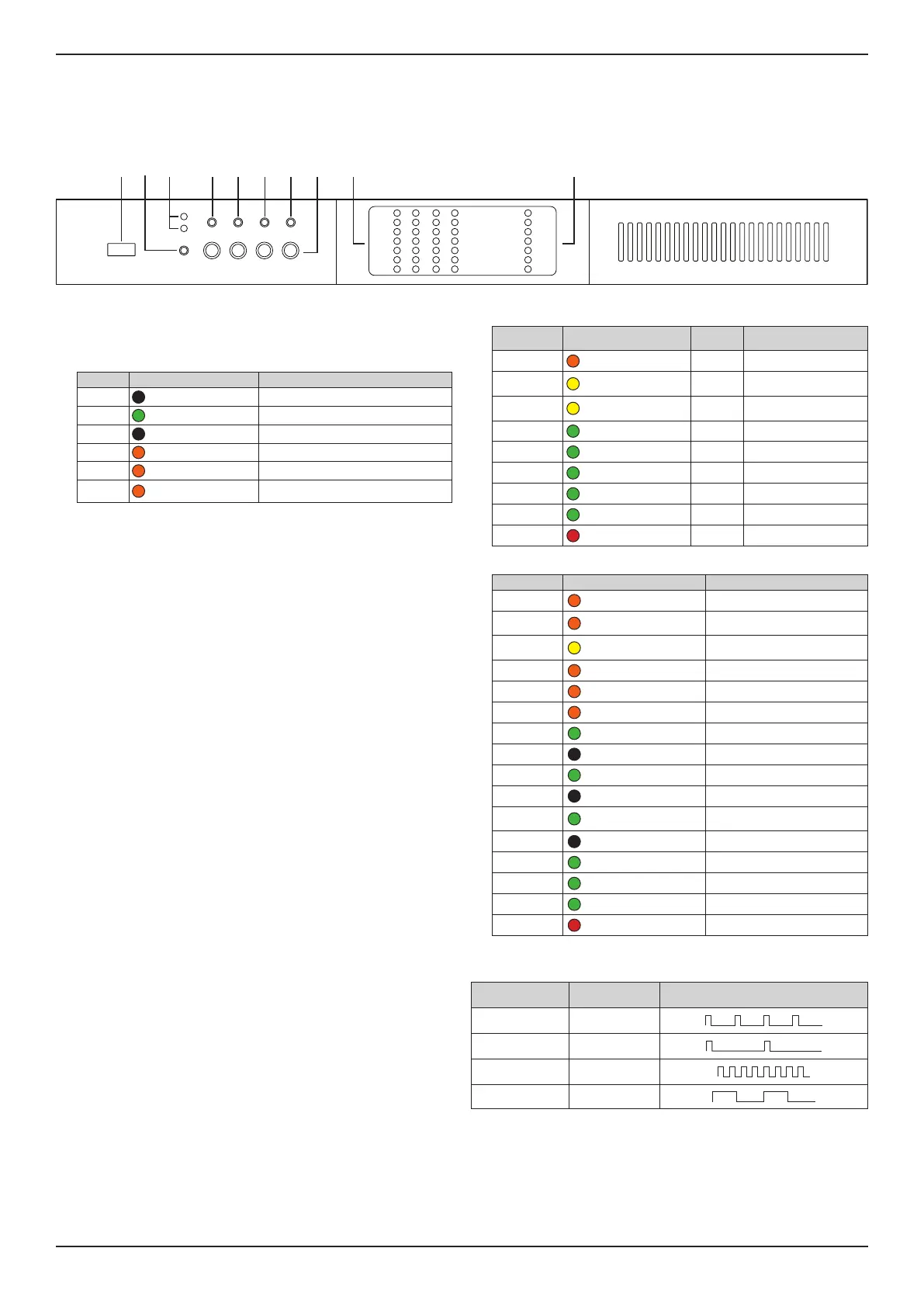
Front Panel (cover removed)
Access the front panel by removing the left faceplate and protective mesh. The faceplate is secured by magnets.
PSX1204D
PWR
CH1 CH2 CH3 CH4
CALL
ON
SDBY
CHECK
CLIP
LIMIT
TEMP
CHECK
REMOTE
MAINS
ALARM
POWER ON
-12dB
-24dB
SIGNAL
READY
ALARM
-6dB/TEMP
SOFT
RESET
HARD
RESET
q w o aire t y u
q Service port: For service only.
w Power button: To switch between system On and Standby mode, press and hold for
three seconds. If desired, the operating condition can be modified by the
GPI/Remote (Remote On/O).
e Operating Mode LEDs: The LED will light green to indicate whether the amplifier is
On or in Standby mode.
LED Light Color & Pattern Indication
ON O Amplifier is powered o
ON Solid green Amplifier is powered on
SBY O Amplifier is powered on
SBY Solid orange Amplifier is in standby mode
SBY Blinking orange Amplifier is in auto-standby mode
SBY
Blink "counter"
(pattern of blinks)
Error code; contact Bose Professional
technical support
r Callback button: Reserved for future use.
t Soft Reset button: Resets network parameters to default settings (DHCP). Press
and hold for three seconds.
y Hard Reset button: Restarts amplifier. Settings and loudspeaker EQs/presets are
unaected. Can be used to cycle power when rear panel is inaccessible. Press and
hold for three seconds.
Note: To reset the amplifier to factory settings (DHCP), press and hold both the
SoftReset and Hard Reset buttons for three seconds. This removes loudspeaker EQs/
presets and resets any adjusted settings.
u Self Check button: For service only.
i Channel Attenuation controls: Attenuation controls for the output level of each
channel. Turn the controls clockwise to decrease attenuation and counter-
clockwise to increase attenuation. Output level can also be adjusted with
ControlSpace Designer.
Note: The attenuation control is in series with the Remote Level connector to limit the
output volume regardless of any remote adjustment.
o Channel Status LEDs: Status LED signal metering for Channels 1, 2, 3, and 4. See the
table below for details.
LED Name Light Color & Pattern
1
Signal
Metering
Other Indication
CLIP Orange Clipping —
–6dB/TEMP Solid yellow –6 dB
Thermal warning; thermal
is protection engaged
–6dB/TEMP
Steady flashing
yellow
–6 dB Auto-standby
–12dB Green –12 dB —
–24dB Green –24 dB —
SIGNAL Solid green –60 dB Signal presence
SIGNAL Blinking green –60 dB Channel is muted
READY Solid green — Channel is ready
ALARM Solid red — Channel fault
a System Status LEDs: System status indicators. See the table below for details.
LED Name Light Color & Pattern
1
Indication
LIMIT Pulse flashing orange Breaker Save is enabled
LIMIT Solid orange
Breaker Save is limiting power
draw
TEMP Solid yellow
Thermal warning; thermal is
protection engaged
CHECK Solid orange System is self-checking
CHECK Blinking orange Self-check is complete
CHECK Fast-blinking orange Self-check is unavailable
REMOTE Solid green Reserved for future use
REMOTE O —
POWER ON Solid green System is ready
POWER ON O System is o
MAINS Solid green
AC mains voltage is within
operating range
MAINS O Under-voltage
MAINS Pulse-flashing green Over-/under-voltage warning
MAINS Fast-blinking green Over-voltage
MAINS Blinking green Blown mains fuses
ALARM Solid red PSU fault or critical faults
Notes:
1. Timing patterns of System Status and Channel Status LEDs:
Lighting Timings Behavior
Pulse flashing
100 ms on
400 ms o
Steady flashing
100 ms on
900 ms o
Fast blinking
100 ms on
100 ms o
Blinking
500 ms on
500 ms o