English • 5Installation Guide • PowerShareX PSX1204D/PSX2404D/PSX4804D
PRO.BOSE.COM
Product Details
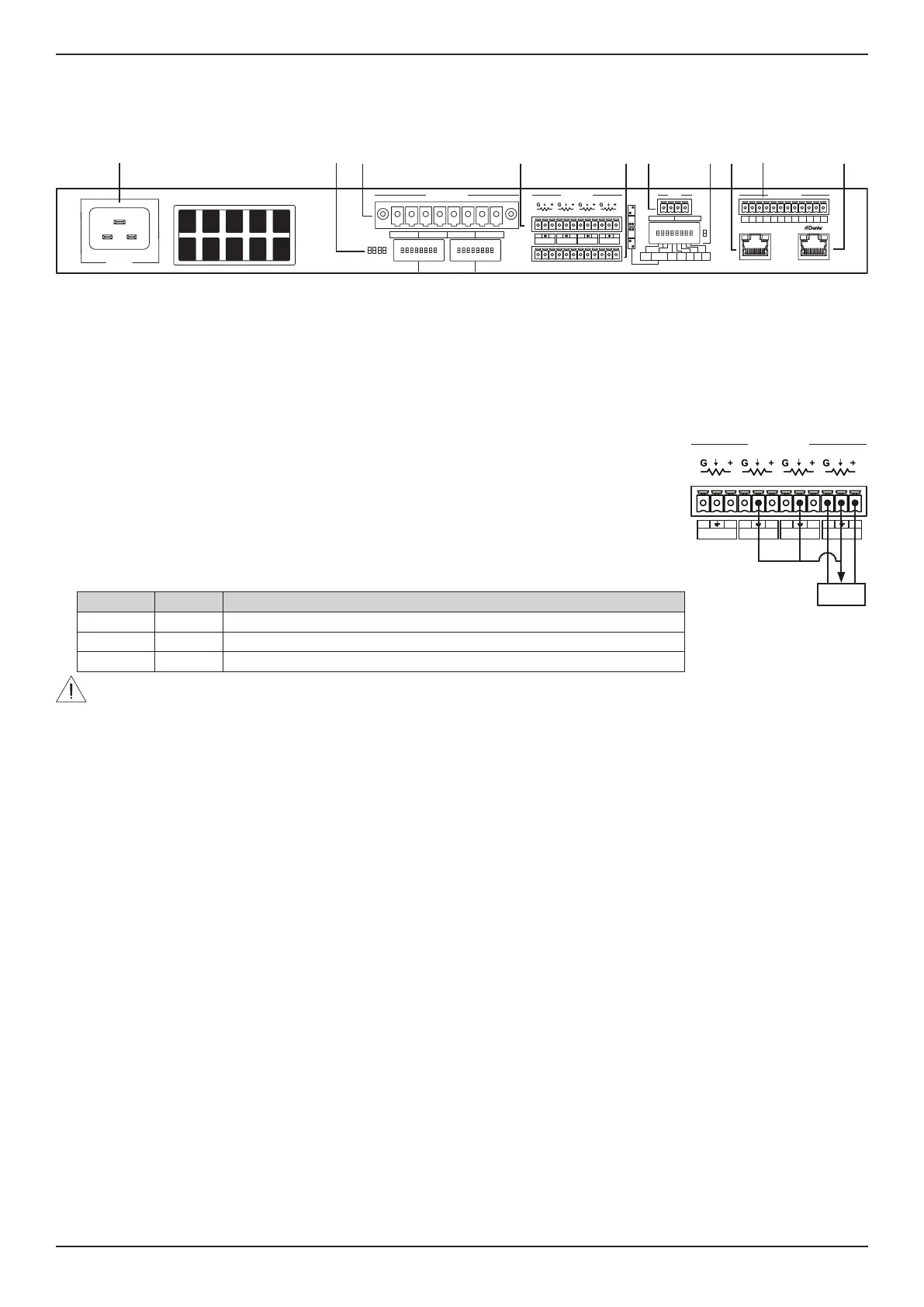
Rear Panel
Ethernet
100V70V
Lo-Z
35Hz
HPF O
Hi-Z
70Hz
HPF On
CH4
+
–
+
–
+
–
+
–
CH3 CH2 CH1
LEVELLINE
OUTPUTS INPUTS
MAINS
ALARM
35dB
32dB
29dB
26dB
GAIN
CH1
MSTR
BRK
SAVE
NRG
SAVE
USR
A
USR
B
CONFIG
2Ω
GPI
CH4
+–
CH3
+–
CH2
+–
CH1
+–
REMOTE ON REMOTE OFF
4NCNONCNONCNONCNO321
ON
OFF
q ow e y ir t u a
q Power input: Power cord connection. Removing the power cord when the amplifier is on is an acceptable power-down method.
w Output Configuration DIP switches: Any mixed configuration of low and high impedance output loads can be made using the four
switches for each channel.
70V/100V: Switch the channel output operation between 70 volts and 100 volts.
Lo-Z/Hi-Z: Switch the channel output impedance between low impedance and high impedance.
35Hz/70Hz: Switch the channel output frequency between 35 Hz and 70 Hz.
HPF O/HPF On: Activate or deactivate the channel output high-pass filter.
e Output connector: An eight-terminal connector for loudspeaker connections. Each channel can deliver up to 300 watts
(PSX1204D), 600 watts (PSX2404D), or 1200 watts (PSX4804D) of power.
r Remote Level connector: The level of each channel can be adjusted remotely by a linear 10kΩ
potentiometer connected to the input LEVEL connector for that channel. Alternatively, to enable
remote level adjustment of multiple channels simultaneously, connect the potentiometer's resistive
variable pin to multiple channels in parallel (refer to the example diagram where the potentiometer
is controlling Channels1–3). The remote level controls are in series with the Channel Attenuation
controls.
Note: ControlCenter CC-1, CC-2, and CC-3 are not compatible with PowerShareX amplifiers.
t Line Input connector: Line-level input for balanced analog audio signals.
y GPI/Remote connector: Remote on and o control. Both pair of terminals respond to the dierential
voltage between the contacts: a voltage dierence between 5 VDC and 24 VDC triggers the control.
The terminals act dierently depending on the actual state of the amplifier:
Remote On Remote O Amplifier State
ΔV ≥ 5V Any Force-turn on; amplifier enters standby mode and will be muted.
ΔV < 3V ΔV ≥ 5V Force-turn o; amplifier exits standby mode and will be unmuted.
ΔV < 3V ΔV < 3V No change (keep either standby or current state).
CAUTION: Any voltage exceeding 28 VDC may damage the input circuitry.
u System Configuration DIP switches: DIP switches to control overall system output and performance.
CH1 MSTR: When the CH1 MSTR switch is OFF, remote-level potentiometers work independently for each channel. When the CH1
MSTR switch is ON, the remote-level potentiometer of Channel 1 acts as a master level, controlling the volume of all four channels.
GAIN: Adjust the gain sensitivity to 35 dB, 32 dB, 29 dB, or 26 dB by following the configuration diagrams on the rear of the
amplifier. This feature is designed to match the voltage of the input signal.
BRK SAVE (Breaker Save): Switch to ON when (1) the power grid is unable to provide enough current to continuously drive the
loads, or (2) when at least one of the amplifiers connected to the same outlet can reach the critical power absorption of the line.
When activated, the Breaker Save halves the maximum continuous current absorption from the mains, which reduces the available
output power. This will aect overall performance of the amplifier.
NRG SAVE (Energy Save): The power supply unit allows a reduction in power consumption when the input signal falls under a
defined threshold. When ON, Energy Save is active on each channel independently. If the signal is absent for more than 30 minutes
on all channels, auto standby is applied and the main PSU is turned o to further conserve energy (Time out time is selectable via
ControlSpace Designer). Normal operation resumes when an incoming signal is detected.
USR A: This feature is unavailable.
USR B: This feature is unavailable.
USR C: This feature is unavailable. Note: PSX4804D only.
2Ω: PowerShareX amplifiers are optimized for working with 4Ω output loads, but the 2 switch allows loads down to 2Ω. Switch to
ON to activate an operating condition that optimizes the performance with very low loads by limiting the maximum output voltage
to 85V
Peak
per channel. This aects all output channels set to match low impedance (i.e. in Lo-Z configuration). For optimal 2Ω
performance, switch the Lo-Z/Hi-Z Output Configuration DIP to Lo-Z for all channels.
Note: PSX1204D and PSX2404D only.
i Ethernet port: RJ45 connector. Remotely control the amplifier via an Ethernet connection through a personal computer and
ControlSpace Designer software.
o GPO/Alarm connector: There are general-purpose output connections for each channel: one Normally Open (NO), one Normally
Closed (NC), and one channel number connection that acts as a ground (1–4). At least two connections are required to report
and detect a change (e.g., 3 and NC). When the amplifier is in normal operating condition, the NO contacts are closed and the NC
contacts are open. These contacts are toggled to indicate a potentially dangerous fault, unsafe operating condition, or any fault
preventing normal output channel operation, including the following:
Across all channels: No AC mains (i.e. system shutdown).
Thermal stress: the system temperature is too high and the thermal protection is engaged.
Amplifier is in standby mode.
Aected channels only: Short circuit in output wiring: either the loudspeaker or the line is in short. Alarm is sent out the specific output channel with the short circuit event.
Please see ControlSpace Designer for additional alarm and monitoring options.
a Dante port: RJ45 connector. PowerShareX accepts four input streams from the Dante® connection through the Dante port. Use
a computer running Dante Controller to implement a Dante network. Dante Controller is a software application that manages
devices on the network.
Ethernet
100V70V
Lo-Z
35Hz
HPF O
Hi-Z
70Hz
HPF On
CH4
+
–
+
–
+
–
+
–
CH3 CH2 CH1
LEVELLINE
OUTPUTS INPUTS
MAINS
ALARM
35dB
32dB
29dB
26dB
GAIN
CH1
MSTR
BRK
SAVE
NRG
SAVE
USR
A
USR
B
CONFIG
2Ω
GPI
CH4
+–
CH3
+–
CH2
+–
CH1
+–
REMOTE ON REMOTE OFF
4NCNONCNONCNONCNO321
ON
OFF
10 kΩ