32
DISASSEMBLY PROCEDURE
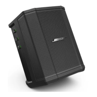
1.5 Use your hands and lift up on the I/O
panel assy.
1.6 Detach the AC cables. See Figure 11.
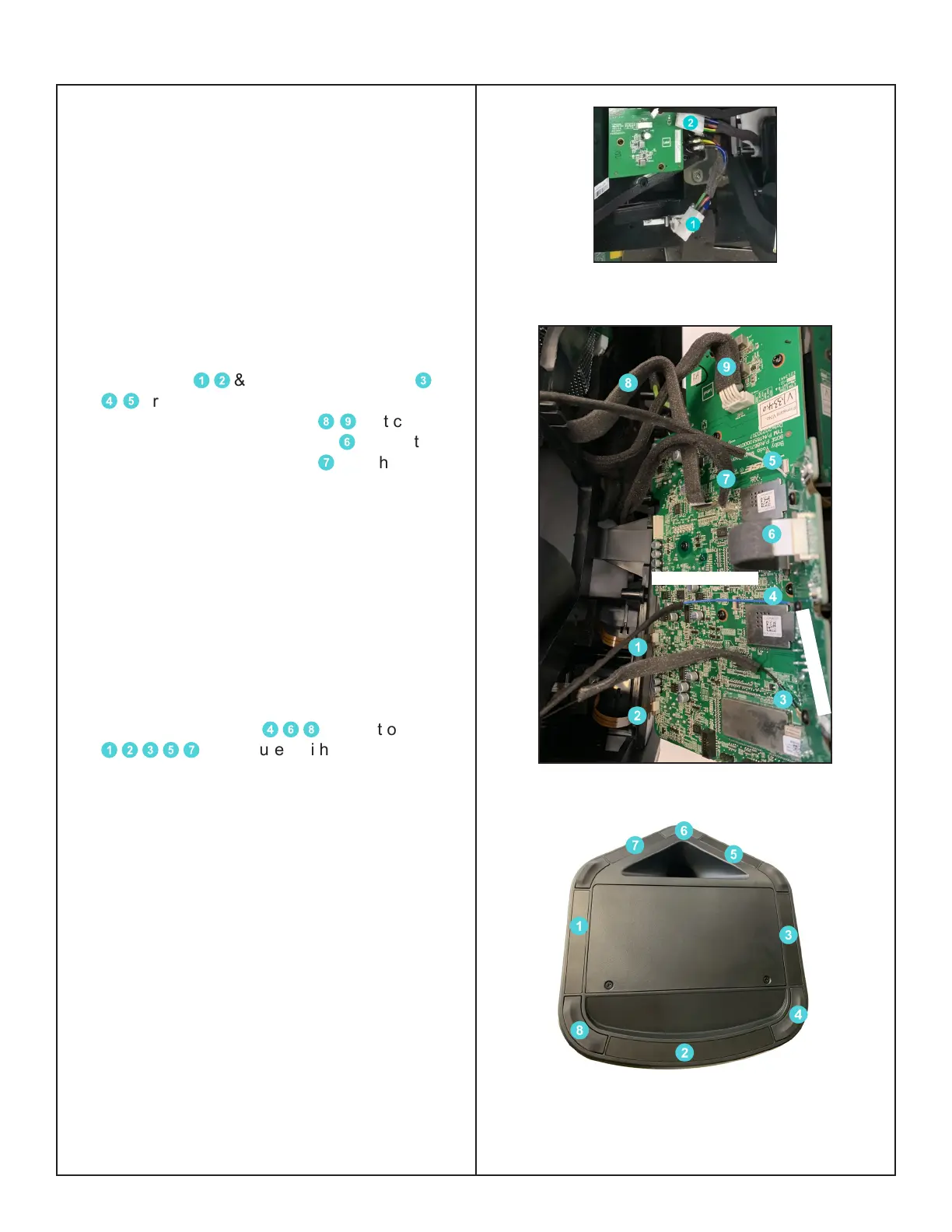
1.7 Once the I/O panel assy is out from the
Cabinet you will notice that the 2 transmitter
FFC cables
1
2
& the 3 Antenna cables
3
4
5
are attached to the Main-I/O board and
the 2 Transducer harnesses
8
9
that connect
to the Power board. FFC cable
6
connects to
the Display board and cable
7
is to the Pole
Switch board. See Figure 12.
Note:
Be careful to not damage the Antenna cables
when removing the glue.
2. Bottom Cover Removal
2.1 Perform procedure 1.
2.2 The Rubber Foot
4
6
8
and Bottom Inlay
1
2
3
5
7
are secured with Pressure Sen-
sitive Adhesive - using a spudger, lift the Feet
and Bottom Inlays up and grasp and pull them
o. See Figure 13.
Re-assembly Note:
a. Makes sure all the old PSA is removed.
b. Clean/wipe the plastic surface with some
isopropyl alcohol and let dry.
c. Install new foot and apply good pressure for
>30 seconds per foot. (It is important as this
will activate the PSA and ensure good adhe-
sion)
Figure 11. Detach the AC cables
Figure 12. FFC Cables Direction
Figure 13. Rubber Feet and Bottom Inlays
Location
Main-I/O Board
Display Board
 Loading...