39
TEST PROCEDURE
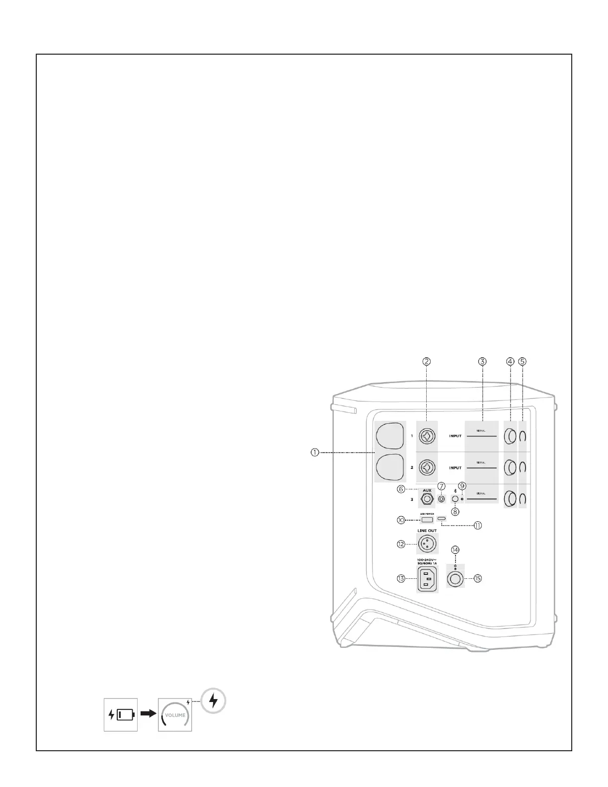
1.1 Press the Power button (15) to turn on
the unit. Verify that the power light (14) which
glows solid white.
1.2 Rotate the Channel 1 Channel Control
knob (4). Verify that the LED’s light on the
Channel display (5) as you rotate.
1.3 Press and hold the Channel 1 Channel
Parameter Control to step through each of
the selections. Verify that the associated
additional controls menu.
1.4 Repeat steps 1.2 and 1.3 for the two
remaining channels.
Note: The Signal/Clip LED’s (3) will be tested
during the signal input tests later in this
procedure.
1.5 Remove the cap (1) and insert the
transmitter into the charging port for Channel
1 & 2. Verify the battery icon with a lightning
bolt next to it briey appears.
Note: A lightning bolt icon then appears in the
upper-right corner of the display.
Required Equipment:
1. Bose S1 Pro+ Wireless PA System (unit under test)
2. Audio Signal Generator, Audio Precision ATS-1 or equivalent
3. iPod Touch/Smart Phone with audio test les / music installed
4. Multi-meter
5. Cables listed below:
- Male XLR audio cable
- 1/8 inch audio cable
- 1/4 inch RS/TRS audio cable
- AC Line cord - per region - refer to packaging part list
6. Bose Wireless Transmitter
Set-up & Connections:
- Connect the Power Stand AC line cord to AC Mains.
Functional Tests:
1. Button and Knob Functionality Test
Refer to the Figure at right for this test
 Loading...