33
DISASSEMBLY PROCEDURE
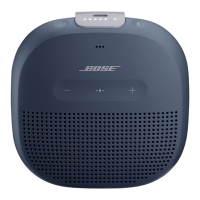
2.3 Remove the 12 screws securing the
Bottom Cover as indicated in Figure 14.
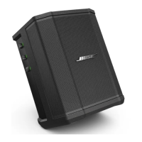
2.4 Once the Bottom Cover is out from the
Cabinet, you will notice that the cable
1
con-
nects to the power port and the cables
2
&
3
attach to the Main-I/O board. The cable
4
is to
the transducer harnesses. See Figure 15.
Note:
• Use a spudger / screwdriver to separate the
white glue from the edge of connections.
• Be careful when regluing the RTV to x the
connections.
2.5 Detach all the board cables from the Pow-
er board.
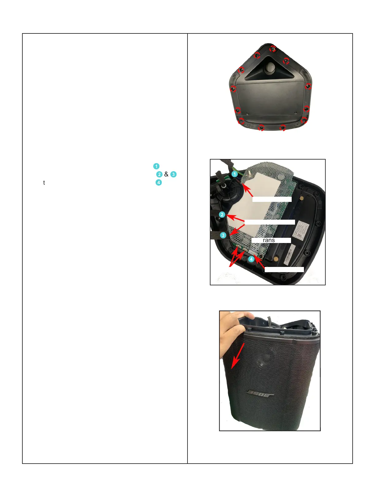
3. Grille Removal
3.1 Perform procedure 2.
3.2 Grasp the Grille and carefully slide the
Grille o of the bae. See Figure 16.
Figure 15. 4 Cables Direction
Figure 16. Grille Removal
To Power Port
To Transducer
Figure 14. 12 screws Location
Blank
To Main-I/O Board
1
2
3
4
To Transducer
 Loading...