Remote Control Unit
2.2 Remote Control Unit
All features of the set-top box can be controlled with the remote controller.
1. POWER
Turns the receiver On/Off.
2. MUTE
Mutes audio output of the receiver.
4. NUMERIC KEY(0-9)
Controls the numerical operation and especially
changes program directly.
5. SAT
Shows satellites list of the searched channels,
change current satellite.
6. TV
Shows the current digital TV program list.
7. RADIO
Shows the current digital Radio program list.
8. FAV
Shows the current favorite program list.
9. TEXT
Shows the list of subtitle and teletext languages
the current channel supports.
10. RECALL
Shows previous channel.
11. UP/DOWN
Change the current program to the previous/next
program in NO-menu state. Moves the cursor to
upward/downward in Menu state.
3. TV/SAT
Control scart output whenever TV/SAT button
is pressed scart output is changed between
receiver output and VCR input.
12. P+/P-
Page up and down in menu list.
13. OK
Activates the highlighted menu item.
Display channel list according to TV/Radio Mode.
14. LEFT/RIGHT
Change the setting value in specific Menu item.
15. INFO
Used for special function. Normally used for viewing channel information.
16. MENU
Shows the menu or sub-menu and cancels the processing function if applicable.
17. EXIT
Exits from the menu or sub-menu and cancels the progressing function if applicable.
18. LANG
Shows the list of the audio language available in the current channel.
19. PAUSE
Pause the video/audio output.
20. EPG
View the program guide in No-menu state.
21. SOUND
Select sound mode to stereo or mono.
16
1
3
7
8
11
14
13
12
15
17
18
21
20
4
5
6
19
9
10
2
11
12
14
13
1
7
8
9
11
5
2
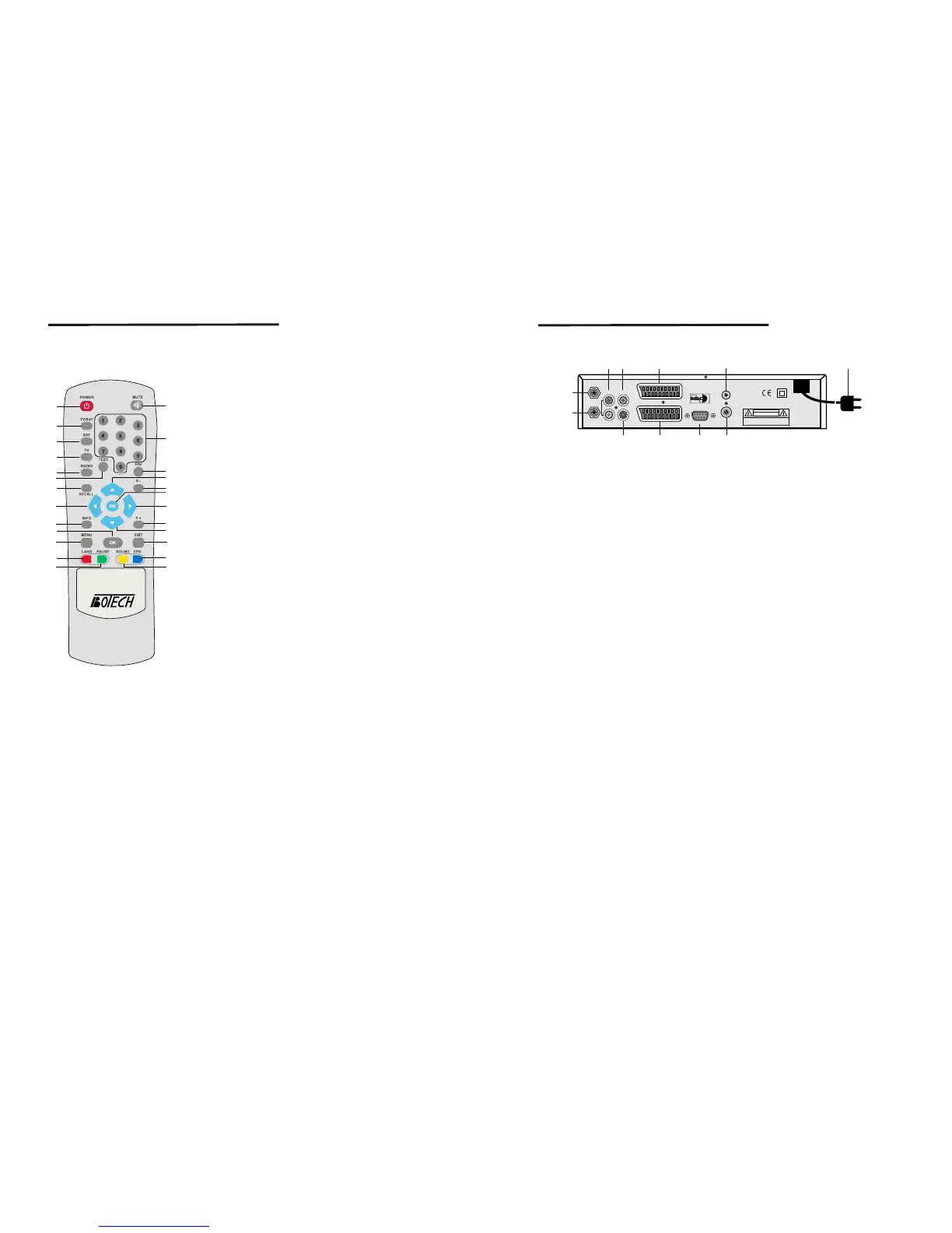
2.3 Rear Panel
1. LNB IN
Connect the digital signal from your LNB of your satellite dish to this connector.
2. LOOP OUT
Gives you the possibility to connect an extra receiver(analogue or digital).
3. AUDIO Right(Red RCA) and Left(White RCA)
These connectors give you the possibility to connect the audio signal to an external
amplifier, or the audio input of your TV.
4. VIDEO(Yellow RCA)
This connector has a constant video signal for additional VCR-connections.
5. DC 0/12V 150mA OUT(Black RCA)
This connector gives you the possibility to get a switched 0/12V, 150mA current
from your receiver for an external positioner.
This RCA can be activated per satellite via the On Screen Display(satellite set-up).
Be carefull in connecting and activating this Black RCA. The 0/12V current can
cause severe damage to your equipment if connected in the wrong way.
6. TV Scart Connector
Use this connector to connect your receiver to your TV using a scart cable.
7. VCR Scart Connector
Use this connector to connect your receiver to your video recorder using a scart cable.
Your video signal will now be looped through to you TV.
8. RS232 Serial Port
This serial port can be used to connect your PC to your receiver, and enables you
to download new versions of software into your receiver.
9. ANT
RF Modulator(female part). If you have an additional antenna(cable or terrestrial)
as well, and you do not use a scart cable to connect the receiver to the TV, then your
additional antenna has to be connected here. If you do use a scart cable to connect
the receiver to your TV, the additional antenna can be put directly into your TV.
10. TV/VCR
RF Modulator(male part). If you do not use a scart cable to connect your receiver
to your TV, you will have to use this connector to connect the receiver to your TV,
using a coax cable. If you connect your receiver to your TV like this, be sure that
you set your TV to the Video channel.
11. Power Cord
Your receiver requires a current of 90~240V AC(Auto-selectable), 50~60Hz+/-5%.
Make sure to check the power specification before connecting your receiver to the
wall outlet.
Figure 3. Rear Panel
Rear Panel
CAUTION
RISK OF ELECTRIC SHOCK
DO NOT OPEN
SHOCK HAZARD : DO NOT OPEN
RISQUE DE CHOC : NE PAS ENLEVER
3
4
6
10
LOOP OUT
AUDIO R
VIDEO
AUDIO L
S/PDIF OUT
TV
VCR
ANT
TV/VCR
RS232
AC 90-240V ~
50/ 60Hz
Max. 30W
Designed by L.A in U.S.A
6
7
 Loading...