51
15.1 Introduction
The user forfeits all rights to claim if
parts other than those of the
manufacturer are used.
We reserve the right to modify design
and performance without prior notice.
Please quote axle number, model and
article number when contacting us with
queries or ordering spare parts.
15.3 KHV7,5 height-adjustable
towing system, model B 3.5.13
The adjustable joint between the
drawbar and intermediate arm, and
between the overrun system and
intermediate arm, consists of toothed
heads or retainers with Hirth-type or radial
serrations.
The radial serrations are secured with
fastening screws. The fastening nut must
be tightened to the specified torque in
order to establish a no-play, torque
15.4 Braking system
Introduction
*
KNOTT over-run brake systems consist
of over-run hitches and wheel brakes
used in combination with KNOTT
torsional thrust spring axles. They are
approved in all countries of the EC and
in Switzerland.
*
With the KNOTT autoreverse system
‘Backmat’ there is no problem changing
the direction of travel from forward to
reverse. The braking system is ready
transmitting connection. The tightening
for immediate operation again when
15.2 Safety
*
It is most important that the wheel and
the hub are compatible dimensionally.
This means that the P.C.D., wheel
bolts and inset must all be compatible
both with the hub and the rim.
Particular attention must be paid to the
recommended torque figures for the
wheel bolts.
*
No welding is permitted on the axle.
*
Please note the swing arm movement.
(See assembly instructions).
*
The wheel brakes are matched to the
overrun devices.
Before using an overrun from another
manufacturer, please check the
compatibility with our Technical -
Department.
Model details must not be obscured by
paint now concealed by components.
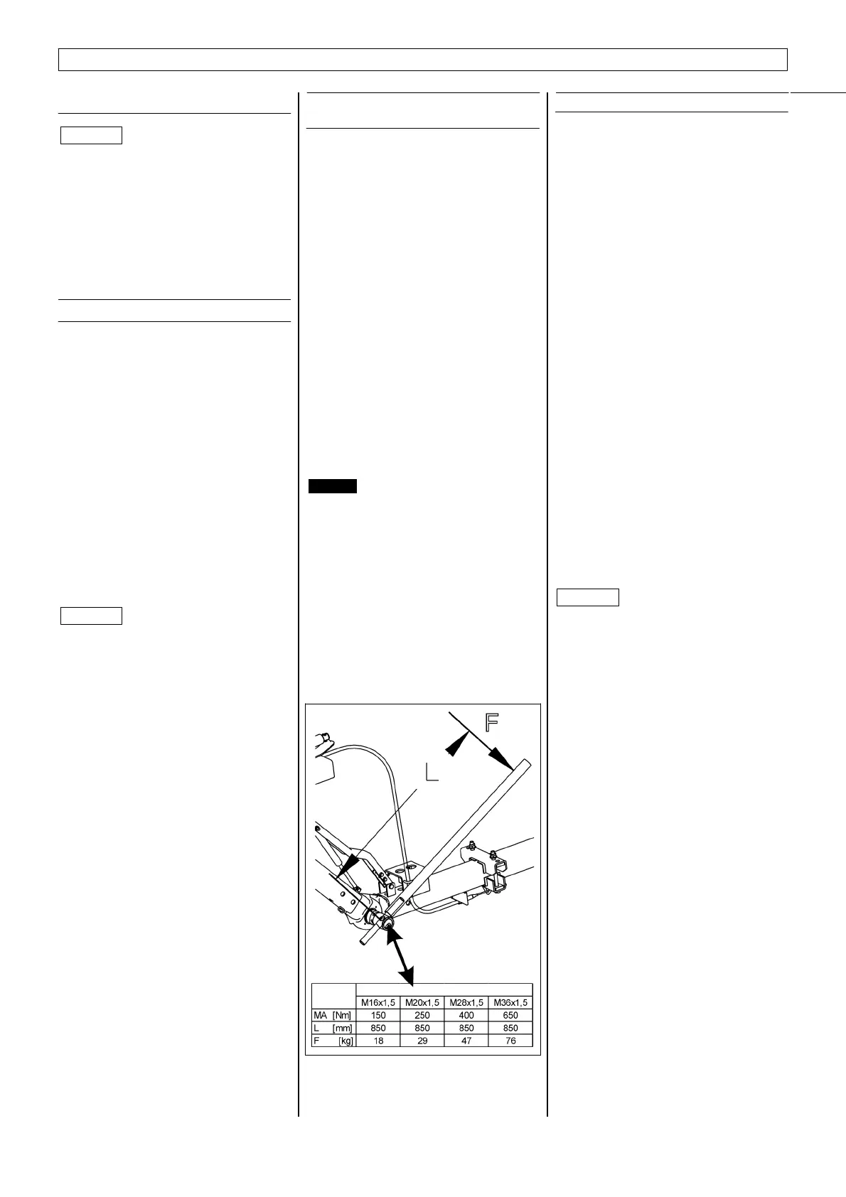
torque depends on the permitted gross
weight of the trailer and the length of
intermediate (swivelling) arm
Adjusting procedure
After the spring-loaded plugs have been
released from the fastening nuts, the nuts
can be loosened until the teeth are
exposed. The angle of the intermediate
arm can then be adjusted.
Danger
Care must be taken without fail to
ensure that the overrun or towing
system is always aligned parallel with
the drawbar.
The vehicle must not be driven unless
the overrun system is parallel with the
drawbar!
After the coupling has been adjusted for
height, the serrations should be locked
together with the clamping nuts and
secured against working loose by means
of the spring-loaded plugs.
Fig. 49
changing from reverse to forward
travel.
* KNOTT torsional thrust spring axles as
well as rubber spring axles have
superb springing and excellent
dampening characteristics. With the
torsional thrust spring axles the spring
elements with their vulcanized rubber
are pretensioned before being pressed
into the axle tubes. There is no
squashing of the rubber during spring
action. Instead the rubber is stretched
in accordance with its characteristics.
With the rubber spring axles theaxle
tube bears the axle by pretensioned
rubber strings. The results of the
stretching are exceptionally long life
and zero maintenance.
Attention
*
Use the jack only under the fixing
brackets or at the chassis, never in
the centre.
*
Towing eye and ball coupling may
only be changed by specialists.
* Use a new safety nut every time one
of these items is changed.
* Use specified torque setting:
Ball coupling
M12 8.8: T = 77 Nm
Towing eyes
M12 10.9: T = 115 Nm
* When using the ball coupling,
please follow the instructions given.
Attention
Attention