12
Assembly Manual
Assembly
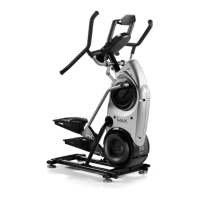
Figure 7-1
Step 7: Attach the Console/
Handlebar Assembly
Parts:
• TreadClimber
®
Base and Treadle assembly from Step 7
• Console/Handlebar Assembly
Hardware:
• (6) 5/16” x 1” Button Head Screws
• (6) 5/16” Flat Washers SAE
Tools:
• 3/16” Hex Key (included)
Note: This step requires two people.
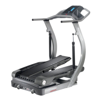
7-1 Lift and position the console/handlebar assembly above
the upright supports (See Figure 7-1).
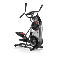
7-2 Put the console/handlebar assembly cable through the top
of the right upright support (See Figure 7-2). Make sure
that the cable extends throught the bottom of the right
upright.
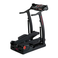
7-3 Put both sides of the console/handle bar brackets into the
tops of the upright supports at the same time. Do not crimp
the cable.
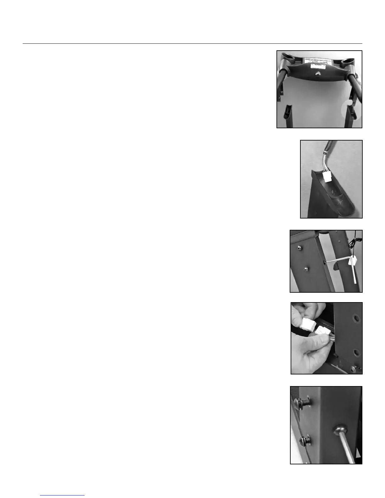
7-4 Tighten the hardware with the 3/16” hex key (See Figure
7-3).
7-5 Connect the cable from the upright support to the cable on
the right side of the base upright bracket (See Figure 7-4).
Repeat this step on the other side.
7-6 One person will hold the Console/Handlebar assembly
while the second person removes the 5/16” x 1” button
head screw at the base of the support from each side.
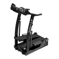
7-7 Lower the upright on to the upright bracket base. Do not crimp
the cables. Drop the upright until flush with the base frame.
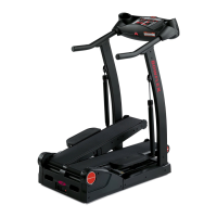
7-8 Attach the upright with (6) 5/16” x 1” button head screws
and (6) 5/16” flat washers SAE.
Note: Tighten the front (2) screws first (1 per upright) and then
the (4) side screws, two per outer side of upright (See
Figure 7-5).
Figure 7-2
Figure 7-3
Figure 7-4
Figure 7-5
 Loading...