Assembly Manual
15
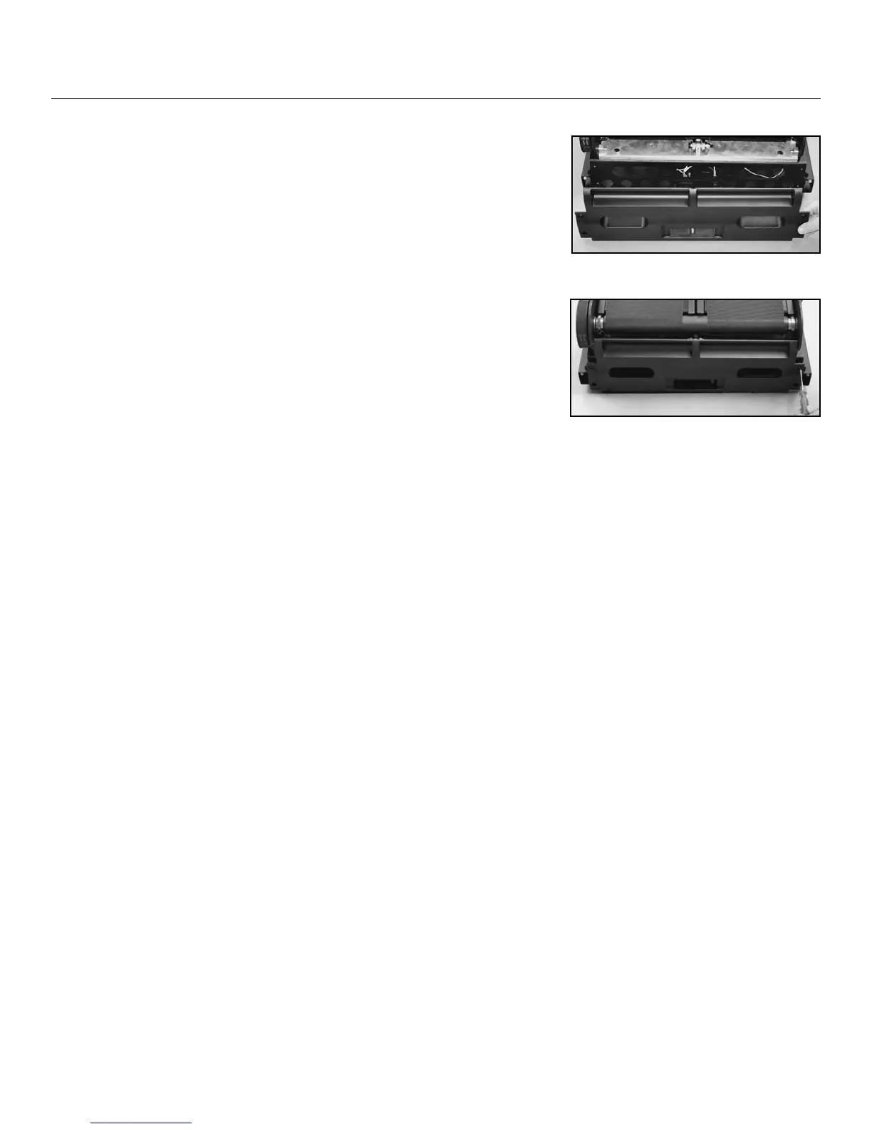
Figure 12-1
Figure 12-2
Step 12: Adjust Speed Sensor and Attach
the Rear Cover
Parts:
• TreadClimber
®
Base and Treadle assembly from Step 11
• (1) Rear Cover
Hardware:
• (4) #10 Phillips Head Screws
Tools:
• #2 Phillips Head Screwdriver (included)
12-1 Hold a stiff business card, ID card, or similar object onto
the inside of the drive pulley. Adjust the speed sensor
towards the card until it just makes contact.
12-2 Remove object.
12-3 Attach the rear cover to the back of the frame with the (4)
#10 Phillips Head Screws (2 per side) and the provided #2
Phillips Head Screwdriver (See Figure 12-1 and 12-2).
Assembly



 To Next Page