16
Assembly Manual
Assembly
Figure 14-1
Figure 14-2
Figure 13-1
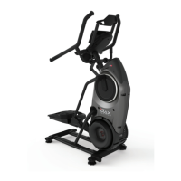
Step 13: Attach the Drive Covers
Parts:
• TreadClimber® Base and Treadle assembly from Step 12
• (1) Left Plastic Drive Cover
• (1) Right Plastic Drive Cover
Hardware:
• (6) #10 Phillips Head Screws
Tools:
• #2 Phillips Head Screwdriver (included)
13-1 Attach the left and right Plastic Drive Covers to the sides of the
base with (6) #10 Phillips Head Screws (3 per side) and the provided
#2 Phillips screwdriver (See Figures 13-1). Install upper screw first.
Note: Do not tighten hardware until all screws have been installed.
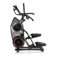
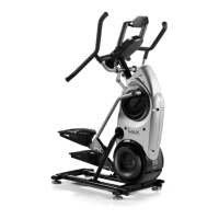
Step 14: Attach the Side Foot
Support Platforms
Parts:
• TreadClimber® Base and Treadle assembly from Step 13
• (1) Left Foot Support Platform
• (1) Right Foot Support Platform
Hardware:
• (6) 1/4” x 1” Flat Head Screws
Tools:
• 5/16” Hex Key (included)
14-1 Attach the right and left side foot support platforms to each treadle
with (6) 1/4” x 1” Flat Head Screws (3 per side) (See Figures 14-1
and 14-2).