A-9
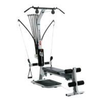
Figure L
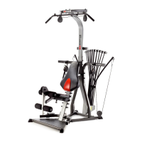
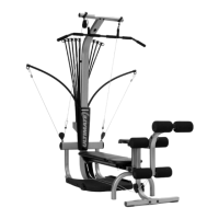
Step 11: ROD BOX INSTALLATION
Locate the following parts for this step:
• Rod box with Power Rods
®
(Item #23)
• Rod box frame (Item #24)
• Three (3) #10X1” self tapping screw
(Item #45)
• Three (3) 1/4” washers (Item #55)
Slide rod box with Power Rods
®
(Item
#23) into rod box frame (Item #24)
as shown in Figure L.
Tighten three (3) #10X1” screws (Item
#45) with three (3) 1/4” washers (Item
#55) through the slot in rod box frame
(Item #24) and into the screw bosses
in the bottom of the rod box with Power
Rods
®
(Item #23) as shown
in Figure L.
23
24
55
45
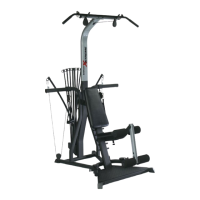
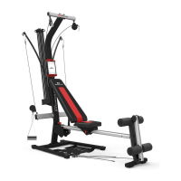
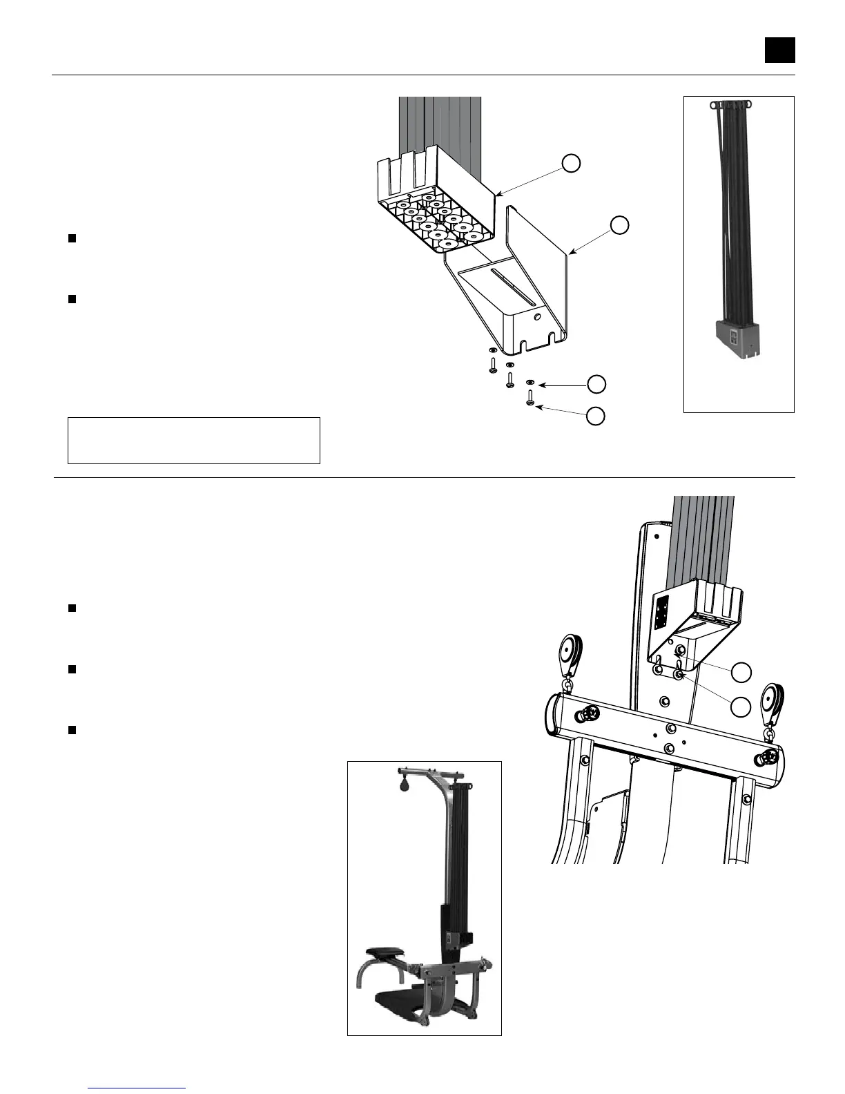
Step 12: ROD BOX FRAME INSTALLATION
Locate the following parts for this step:
• Rod Box with Power Rods
®
with frame (Items #23 & 24)
• Three (3) 3/8”X3/4” bolts (Item #46)
• Three (3) 3/8” washers (Item #54)
Start two (2) 3/8”X3/4” bolts (Item #46) with 3/8” washers
(Item #54) into the lower two holes in the rear of the lower lat
tower (Item #1) as shown in Figure M.
Slide the rod box frame (Assembly #24) onto the two bolts
making sure the rod box frame is behind the washers as shown
in Figure M.
Thread the third 3/8”X3/4” bolt (Item #46) into the top hole of
the rod box frame (Item #24). Securely tighten all bolts.
54
46
Figure M
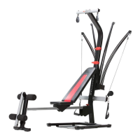
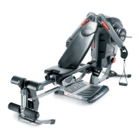
Unit appears like
this following this
assembly step
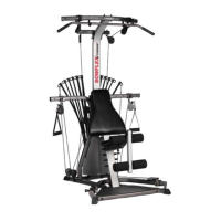
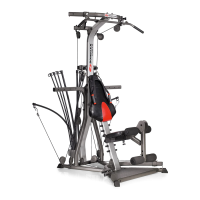
Unit appears like
this following
this assembly
step
(shown with
optional lat
tower)
Components for this step
are in Box 1 & Box 4
CAUTION:
When hooking up the Power Rods
®
,
do not stand directly over the tops of
the rods. Stand off to the side while
connecting and disconnecting the
Power Rods
®
from the cables.
Assembling Your Bowflex
®
Ultimate
™