10
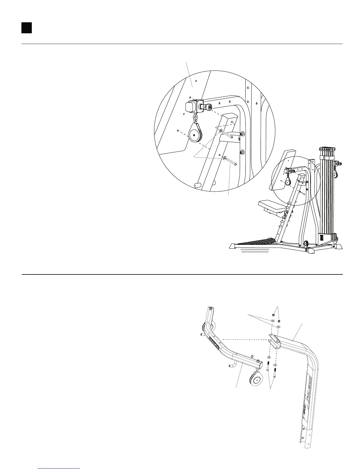
Upper Lat Tower Assembly
Parts:
• Upper Lat Tower
•
Lat Cross Bar
Hardware:
• 2 Button Head Screws (3/8" X 2 1/2")
•
2 Washers (3/8")
Tool:
7/32" Hex Wrench
14-1 Align the two holes on the Lat Cross Bar with
those on the Upper Lat Tower as shown.
14-2 Secure using washers and screws as shown.
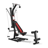
Step 13 Install Seat Back Pad
Note: The back of the Seat Back Pad has two
pairs of hol
es. Select the appropriate
set based on your height.
Parts:
• Seat Back Pad
•
Main Assembly
Hardware:
• 2 Button Head Screws (5/16" X 2 1/2")
•
2 Washers (5/16")
Tool:
3/16" Hex Wrench
13-1
Position Seat Back Pad against the
Seat Support Rail and align the
screw holes for your
height with
those on the Seat Support Rail
.
13-2
Secure Seat Back Pad to the Seat
Support Rail using screws and
washers as
shown.
Seat Back Pad
Flat
Washer
s
Button
Head
Screws
Button Head
Screws
Flat
Washers
Lat Cross Ba
r
Uppe
r Lat Tower
Hex Nuts