Do you have a question about the Branson Sonifier 250 and is the answer not in the manual?
Crucial safety precautions to observe when operating the Analog Sonifier.
Explains signal words like WARNING, CAUTION, NOTICE.
Lists applications and power differences between 250W and 450W Sonifiers.
Details compliance standards for Sonifiers sold in Europe.
Outlines the terms, conditions, and exceptions of the product warranty.
Provides contact information for customer service, technical support, and parts.
Lists information to prepare before contacting Branson for support.
Details the procedure and requirements for returning equipment for repair.
Explains how to contact the Parts Store and what information is needed.
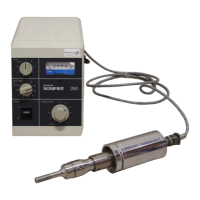
Identifies the primary components of the Sonifier unit.
Explains how the Sonifier converts electrical energy into mechanical vibrations.
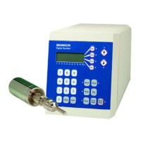
Details the devices and functions on the front panel of the power supply.
Describes the components and connections on the rear panel.
Instructions for unpacking the unit and inspecting for shipping damage.
Guidance on selecting a suitable location for the Sonifier unit.
Specifies the required single-phase voltage and frequency for operation.
Step-by-step guide for setting up the converter/horn assembly.
Procedure for establishing a baseline for future equipment testing.
Instructions for attaching and detaching horns and tips.
Details on how to correctly connect the horn to the converter.
Steps for attaching a tip to the horn, including torque specifications.
Information on necessary guards and personal protective equipment.
Details electrical, mechanical, and dimensional specifications for the Sonifier.
Lists electrical specs like voltage, frequency, power, fuse, leakage.
Provides weight and dimensions for converter and power supply.
Shows side and front view dimensions of the Sonifier unit.
Explains basic operation modes: Timed, Continuous, and Pulsed.
Describes setting the timer for specific processing durations.
Details how to set the unit for continuous operation.
Explains the pulsed mode and duty cycle control for temperature management.
Discusses techniques for optimal ultrasonic processing and temperature control.
Covers methods to manage sample temperature during operation.
Relates vessel size to cooling requirements and temperature rise.
Addresses issues like foaming, aerosoling, and discoloration.
Instructions for sterilizing horns and tips.
Techniques for processing biological tissues and solid materials.
How to use glass powders to enhance cell disruption.
Details amplitudes for various horn and micro tips.
Directs users to contact support for maintenance needs.
Covers periodic inspection and maintenance of tooling components.
Explains tip erosion, its causes, and signs of wear.
Discusses causes of power loss and initial troubleshooting steps.
Outlines periodic cleaning of the equipment.
Describes how to maintain the converter-horn mating surfaces.
Details the process of cleaning and reconditioning mating surfaces.
Instructions for replacing the stud on the horn/converter assembly.
Steps for cleaning the threads of the horn tip.
A chart to diagnose symptoms and probable causes of system issues.
3 minutes of sonifying produced excellent disruption with 50% protein released.
Excellent breakage with better enzyme release than other methods.
10 ml concentrated solution completely disrupts in 1 minute.
Extraction from ipecac root yielded more alkaloid than Soxhlet extraction.
Monocellular elements from surface-grown colonies obtained in 1 minute.
Used extensively to produce antigens and vaccines, increasing yield.
1 gram disintegrates in 2 minutes.
8 ml concentrated solution completely disrupts in 4 minutes.
Lists replacement parts like fuses, washers, studs, converters, and wrenches.
Useful for processing small volumes, available in tapered and double-stepped designs.
Allows treatment in small tubes without immersing the horn, ensuring sterile conditions.
Designed for pharmaceutical research, allows continuous processing or mixing.
Conical glass cell for exposing substances to ultrasonic energy during circulation.
Allows continuous processing of low-viscosity materials for emulsifying/dispersing.
Reduces mechanical noise generated during ultrasonic processing.
Lists disruptor horns and their EDP numbers.
| Power Output | 250 watts |
|---|---|
| Frequency | 20 kHz |
| Amplitude Range | 0-100% |
| Timer | 1 second to 15 minutes |
| Voltage | 115/230 V, 50/60 Hz |