The Series 54 Proximity Sensors are designed to provide valve position indication using various signal types. These sensors utilize solid-state switches to monitor the position of rotary devices, offering a contactless indication system. An activator, mounted onto the actuator's center pinion, rotates as the valve is actuated, measuring open and close positions. Metal inserts within the activator activate corresponding inductive switches in the sensor, relaying valve position to the end user and illuminating an LED.
Function Description:
The primary function of the Series 54 Proximity Sensor is to monitor and indicate the open and closed positions of a valve. It achieves this through a contactless inductive sensing system. When a metal insert on the activator is in proximity to a switch, it triggers a signal (either open or closed) and illuminates a corresponding LED. The sensors are designed to be compatible with various control systems, and their electrical characteristics, such as operating voltage, maximum switching current, output voltage drop, and residual current, must be carefully considered during installation to prevent damage and ensure proper operation. All activators can be configured for either clockwise or counter-clockwise valve operation.
Important Technical Specifications:
The Series 54 Proximity Sensors are available in various electrical output configurations:
- DC 3-wire PNP: Models 540001-71104533, 540021-71104533, 540041-71104533
- Intrinsically Safe: Models 540003-71104533, 540013-71104533
- AC/DC: Model 540004-71104533
- ASi-Interface + Out: Models 540005-71104533, 540015-71104533
- DC 2-wire: Models 540022-71104533, 540032-71104533
- DC 2 Wire - Hazardous Location + Out: Model 540102-71104533 (included in kit PN54010-126XX536)
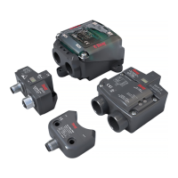
Housing Options:
- Large Housing with Connector
- Large Housing with Conduit Entry
- Small Housing with Connector
- Small Housing with Conduit Entry
- Large Housing with Rd24 Connection
Activator Kit Numbering:
Activators are categorized by type (Adjustable, Non-Adjustable, High Visibility), actuator size (e.g., S92/93, 63-128, 160-210, 255), and thread type (Imperial or Metric).
Cable Gland Connections:
M20 cable gland connections are found on specific sensor models (540032-71104533, 540013-71104533, 540015-71104533, 540102-71104533).
Acceptable wire size gauge (single conductor per terminal):
- General: 16 to 28AWG
- Industrial: 14 to 22AWG
- Hazardous: 14 to 22AWG
Usage Features:
- Contactless Indication System: Utilizes inductive sensors for reliable position monitoring without physical contact.
- Adjustable Activators: For customers requiring flexibility, adjustable activators allow positioning of indication limits outside standard zero to ninety degrees in five-degree increments. This is achieved by loosening an allen head bolt, rotating the relevant piece, ensuring the yellow indicator matches the valve disc position, and then tightening the bolt.
- High Visibility Activators: These activators require removal of the cover bolts and cover, loosening the center allen head bolt, rotating the activator piece to the desired rotation, ensuring the open and close activator is visible when the cover shield is installed, re-tightening the bolt, and reinstalling the cover and mounting bolts.
- Multiple Connection Options: Bray offers three connection types:
- Sensor Only: Supplies sensor power and signal output.
- Sensor and Solenoid (Shared): Uses Y-connectors for solenoid control on sensors without dedicated solenoid outputs, with the system side line carrying both sensor and solenoid power.
- Sensor and Solenoid (Independent): Sensors with dedicated solenoid outputs, where sensor signal and solenoid power are transmitted on the main system side line, and the solenoid is activated via power supplied from the sensor through an S-connector.
- Hazardous Location Kits: Specific kits are available for hazardous environments, including protective covers and appropriate hardware.
- Compatibility: The electrical characteristics of the S54 must be compatible with the application's operating voltage, maximum switching current, output voltage drop, and residual current to prevent damage and void warranty.
Maintenance Features:
- Pre-installed Storage Guidelines: Units are not weatherproof until properly installed. For storage, all conduits and port connections must be sealed. Store indoors in a well-ventilated, clean, dry room between 40°F (4°C) and 85°F (29°C) with less than 70% relative humidity. Protect from vibration, direct sunlight, dampness, dust, and dirt. For long-term storage, placing the unit in a plastic sealed bag is recommended.
- Installation Guidelines for Cable Glands: Cable glands must be certified for the application, with a temperature range selected accordingly. The ingress protection rating must not be reduced. Gland connections must be properly sealed.
- Drainage for Wiring Conduit: If mounted on a vertical pipe, the sensor should be positioned with cable glands at the bottom to prevent condensation. Adequate drainage of wiring conduit is essential to prevent water contamination inside the sensor.
- Required Tools for Adjustment and Installation:
- #5 Hex key wrench
- #4 Hex key wrench
- 5/32 Hex key wrench
- Philips screwdriver, 3/16"
- Flat screwdriver, 1/8"
Safety and Operational Notes:
- Always turn off all power and lockout/tag out service panels before installing or modifying any electrical wiring.
- Solid-state switches have current restrictions (typically half an ampere or less) due to semiconducting materials, unlike mechanical switches that can handle several amperes.
- Output voltage drop must be considered, especially when connecting multiple sensors in series or over long distances, to ensure the last sensor receives sufficient operating voltage.
- Residual current (leakage current) in the "off" state must be below the control system's maximum off-state current rating.
- Proper configuration and calibration are required for safe operation.
- The control system must have safeguards to prevent injury or equipment damage in case of component failure.
- Only qualified personnel familiar with installation, commissioning, and operation of the product, and trained in relevant safety practices (pneumatic pressure equipment, electrical circuits, PPE, first aid, hazardous locations), should handle the device.