Brent 1082/882 — Maintenance
4-12
Verify Telescoping PTO Shaft Length
• PROPERLY EXTENDED AND COLLAPSED LENGTHS OF THE TELESCOPING PTO SHAFT
MUST BE VERIFIED BEFORE FIRST OPERATION WITH EACH AND EVERY DIFFERENT
TRACTOR. IF THE EXTENDED LENGTH OF THE PTO SHAFT IS NOT SUFFICIENT, IT
MAY BECOME UNCOUPLED IN OPERATION AND CAUSE SERIOUS INJURY OR DEATH
FROM CONTACT WITH UNCONTROLLED FLAILING OF PTO SHAFT ASSEMBLY COM-
PONENTS.
An excessive collapsed length can result in damage to the PTO driveline and attached components.
This is most likely to occur during extreme turning angles and/or travel over rough terrain. Conditions
are amplifi ed on tractors with tracks operating in uneven terrain, particularly rice levies.
Damaged driveline components can result in unsafe operation and severely reduced driveline
component life.
NOTE: Do not exceed 10 degrees beyond a straight pull line while operating the PTO.
To verify proper extended and collapsed lengths, use the following procedure:
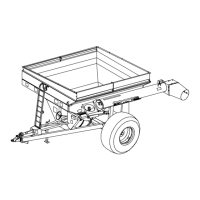
1. Fully collapse PTO shaft and measure length
“L” (Fig. 4-13).
Enter here: (1) (Verify that outer
tube does not bottom out on surrounding plas-
tic shield components).
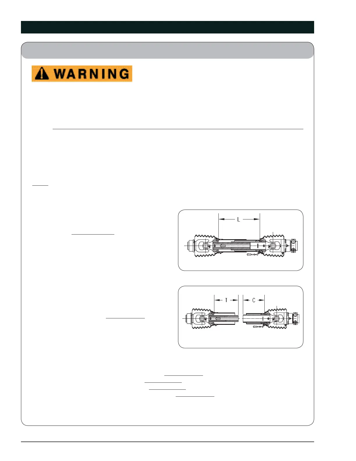
2. Pull apart PTO telescoping shaft ends and
measure lengths “T” & “C” (Fig. 4-14).
Add “T” &”C” measurements together
Enter total here: (2)
3. Calculate maximum recommended extended length:
a. Subtract line 1 from line 2. Enter here: (a)
b. Divide line (a) by 2. Enter here: (b)
c. Add line (b) to line 1. Enter here: (c)
d. Subtract 3 inches from line (c). Enter here: (d)
This is the maximum recommended extended length (LB).
(April 2015)
Fig. 4-13
Fig. 4-14
 Loading...