17
Status LED’s
Described below are the system’s LED indicators and the
conditions each LED color represents:
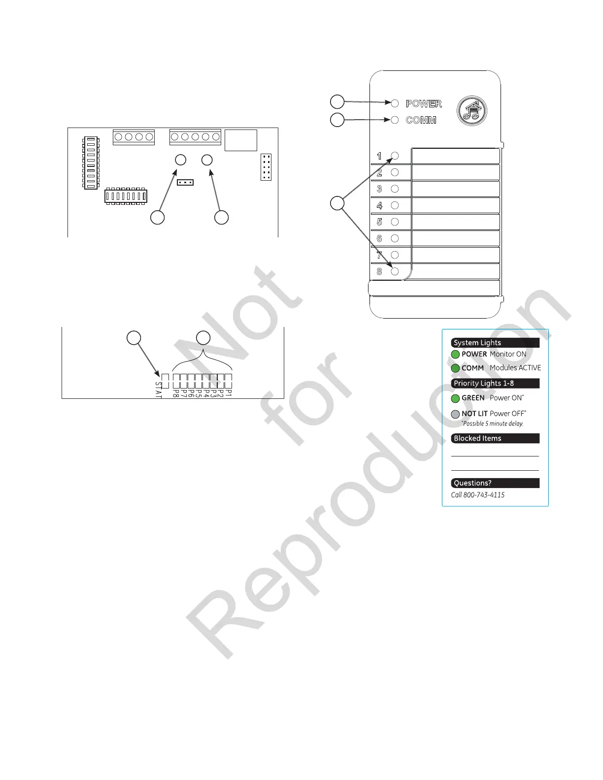
Transfer Switch Control Board
STATUS LED
RED (A) means GENERATOR power is present.
GREEN (B) means UTILITY power is present.
Symphony II System Control Board
STATUS LED (C)
Single Blink-Pause means unit is operating on
GENERATOR power.
Double Blink–Pause means unit is operating on
UTILITY power.
PRIORITY LIGHTS/LED’s (D & G)
When green LED is lit, indicates that optional remote module
set to that priority is supplying power to connected load
during generator power.
When not lit, indicates that optional remote module set to
that priority is set to OFF (being managed and Symphony II
System is not allowing power to the unit).
All lights/LED’s are OFF when utility power is present.
Symphony II Power Monitor (Optional)
POWER LIGHT (E)
When lit, indicates that monitor
detects outlet power.
When not lit, indicates that no
power is present at outlet.
COMM (communication
status) LIGHT (F)
When lit, indicates that unit
is receiving signals from the
Symphony II controller.
When not lit, indicates that
utility power is present or a
fault in Symphony II controller.
A
B
E
F
G
312113
LED
LED
LED
LED
LED
LED
LED
LED
LED
C
D
 Loading...