98
6
6
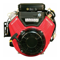
Figure 18
NOTE: Do not torque each screw in one step as
it may result in a warped cylinder head. Step-
torque all screws to approximately 1/3 of final
torque value, then to 2/3 final torque value, then
finish at final torque value.
3. Install push rod guide and rocker arm
studs (models 97700, 99700). Torque
studs to values listed in Section 12 -
Engine Specifications.
-OR-
4. Install rocker arm studs (models 110000,
120000, 150000). Torque to values listed
in Section 12 - Engine Specifications.
NOTE: Early production of vertical models
110000 and 120000 require a jam nut to be
threaded approximately half way up the threads
of the stud before installation into the head.
5. Install push rods through guides and into
same positions as removed. Ensure rods
are seated in valve tappets. Place valve
stem caps (if used) on valve stems.
6. Place rocker arms and rocker balls on
rocker arm studs (Figure 19). Install rocker
arm screws and/or lock nuts on studs and
tighten until there is zero clearance
between the valve stem caps and the
rocker arms.
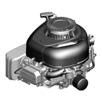
Figure 19
7. Rotate crankshaft at least twice to ensure
proper movement of the push rods and
rocker arms.
8. Adjust valve clearance per Section 1, then
install a new rocker cover gasket and the
rocker cover. Torque screws to values
listed in Section 12 - Engine
Specifications.
 Loading...