16
1
1
ENGINE ADJUSTMENTS
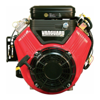
Remote Control Wire Travel
The remote control wire should measure 2.125”
(54 mm) when extended outside the casing
(Figure 21). After installation, the travel of the
remote control wire must be at least 1.375” (35
mm) to properly actuate the choke (on Choke-A-
Matic® systems) and the ignition stop switch (if
equipped).
Figure 21
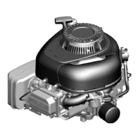
Remote Controls
Horizontal Models 110000, 120000, 150000
1. Loosen casing clamp screw
(A, Figure 22).
2. Move throttle lever to fast position.
3. Move casing in direction of arrow until
slack is removed.
4. Tighten casing clamp screw.
Figure 22
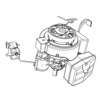
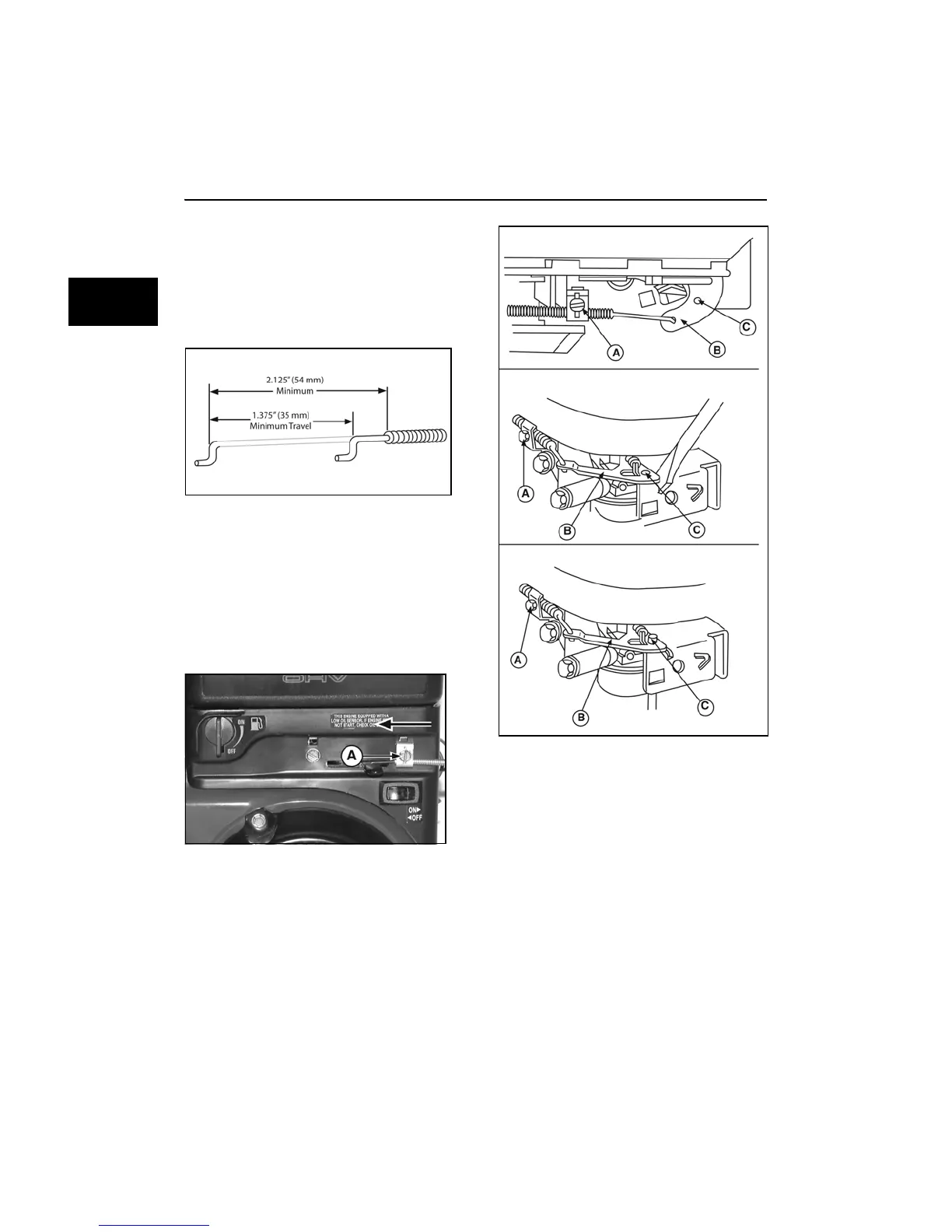
Vertical Models 97700, 99700
1. Loosen casing clamp screw (A, Figure 23)
on intake elbow assembly.
Figure 23
2. Move equipment speed control lever (B) to
FAST position.
3. Move control wire and casing at governor
bracket to align hole (C) in carburetor
control lever with hole in carburetor control
bracket.
4. Tighten casing screw.
 Loading...