95
6
6
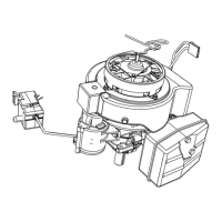
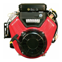
Figure 6
3. Remove push rods one at a time, marking
the location and orientation of each for
proper installation later.
4. Using a plastic scraping tool, carefully
clean all traces of head gasket from the
head and cylinder mating surfaces.
Disassemble Cylinder Head
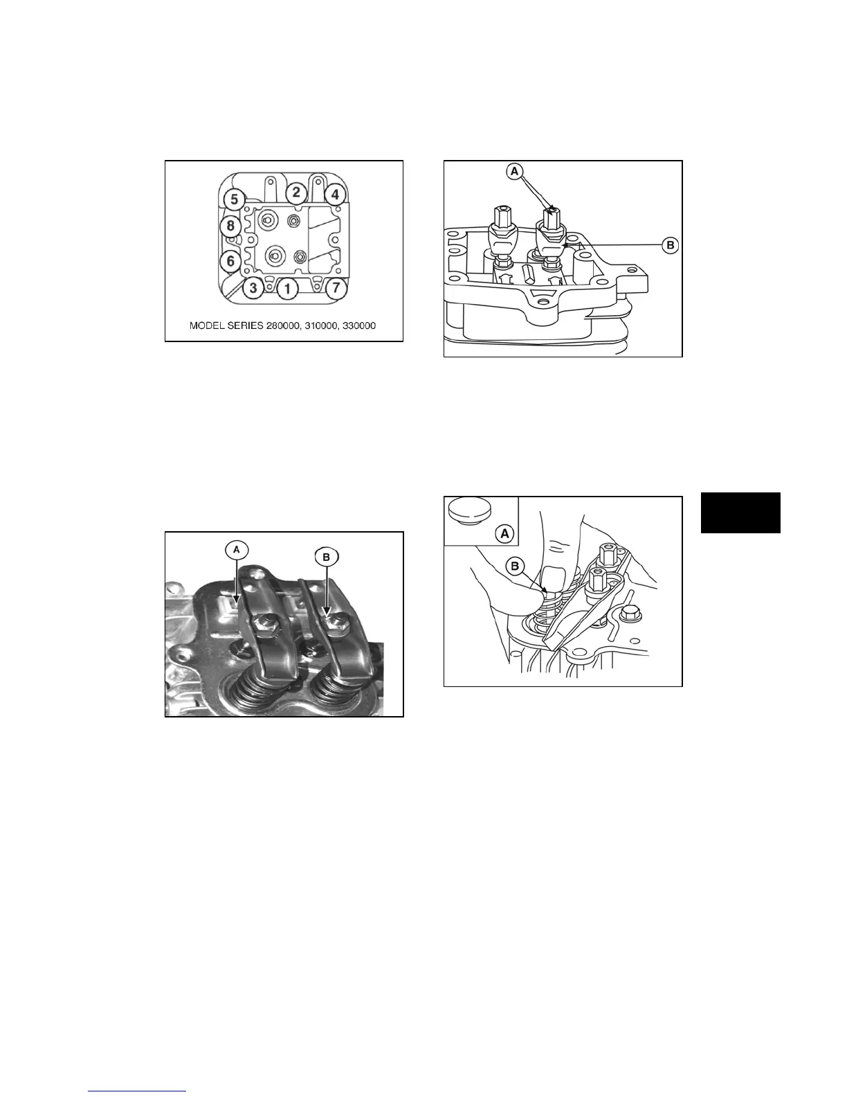
1. Loosen rocker arm screws and/or lock
nuts (A, Figure 7 and 8), and remove from
rocker arm studs. Remove rocker arms
(B) and rocker balls from studs.
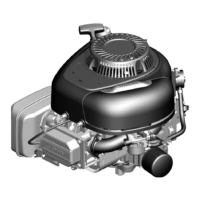
Figure 7
Figure 8
2. Remove valve stem caps (A, Figure 9) (if
used), the rocker arm studs, and the push
rod guide (models 97700, 99700).
3. Using thumbs, press down on each valve
spring retainer and disengage retainer
from valve stem (B). Remove retainers,
springs, valves, and intake valve stem
seal/washer, if equipped.
Figure 9
4. Remove push rod cylinder head plate and
plate gasket (models 110000, 120000,
150000). Remove and discard the plastic
push rod guides from the head plate.
Inspection
1. Visually inspect head for cracks,
excessive heat discoloration, warping of
the cylinder or rocker cover mating
surfaces, and burned or damaged valve
seats. Replace head, if any of these
problems are found.
 Loading...