Assembly
Read entire operator’s manual before you
attempt to assemble or operate your new
pressure washer.
Your pressure washer requires some assembly and is
ready for use after it has been properly serviced with
the recommended oil and fuel.
If you have any problems with the assembly of your
pressure washer, please call the pressure washer
helpline. If calling for assistance, please have the
model, revision, and
serial number from the
identification label available.
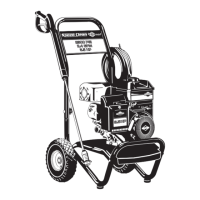
Unpack Pressure Washer
1. Remove the parts bag, accessories, and inserts
included with pressure washer.
2. Open carton completely by cutting each corner
from top to bottom.
3. Ensure you have all included items prior to
assembly.
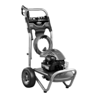
Items in the carton include:
• Main Unit
• Handle
• High Pressure Hose
• Spray Gun
• Nozzle Extension with Quick Connect Fitting
• Oil Pouch (2)
• Parts Bag (which includes the following):
• Operator’s Manual
• Ba g containing 5 Multi–Colored Spray Tips
• Handle Fastening Hardware
Kit (which
includes):
• Carriage Bolts (2)
• Plastic Knobs (2)
To prepare your pressure
washer for operation,
you will need to perform these tasks:
1. Attach handle to main unit.
2. Add oil to engine crankcase.
3. Add fuel to fuel tank.
4. Connect high pressure
hose to spray gun and
pump.
5. Connect water supply
to pump.
6. Attach nozzle extension to spray
gun.
7. Select/attach quick connect spray tip to nozzle
extension.
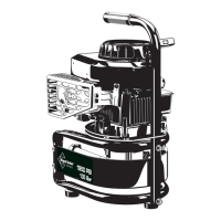
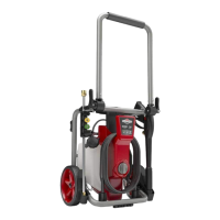
Remove Pump Oil Shipping Cap
A shipping cap has been installed on the pump to
prevent oil from leaking.
NOTICE Failure to install vented plug/dipstick will
result in a pump failure and void the warranty.
1. Remove the red shipping cap (A) from pump.
2. Install the vented plug/dipstick (B) in the pump.
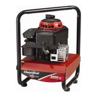
Attach Handle
1. Place handle (C) onto handle supports (D)
connected to main unit. Make sure holes (E) in
handle align with holes (E) on handle supports.
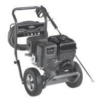
2. Insert handle carriage bolts (F) through holes from
inside of unit and attach a plastic knob (G) from
outside of unit. Tighten by hand.
3. Insert multi–colored spray tips in spaces provided
in handle.
G
F
E
C
D
E
B
A
 Loading...