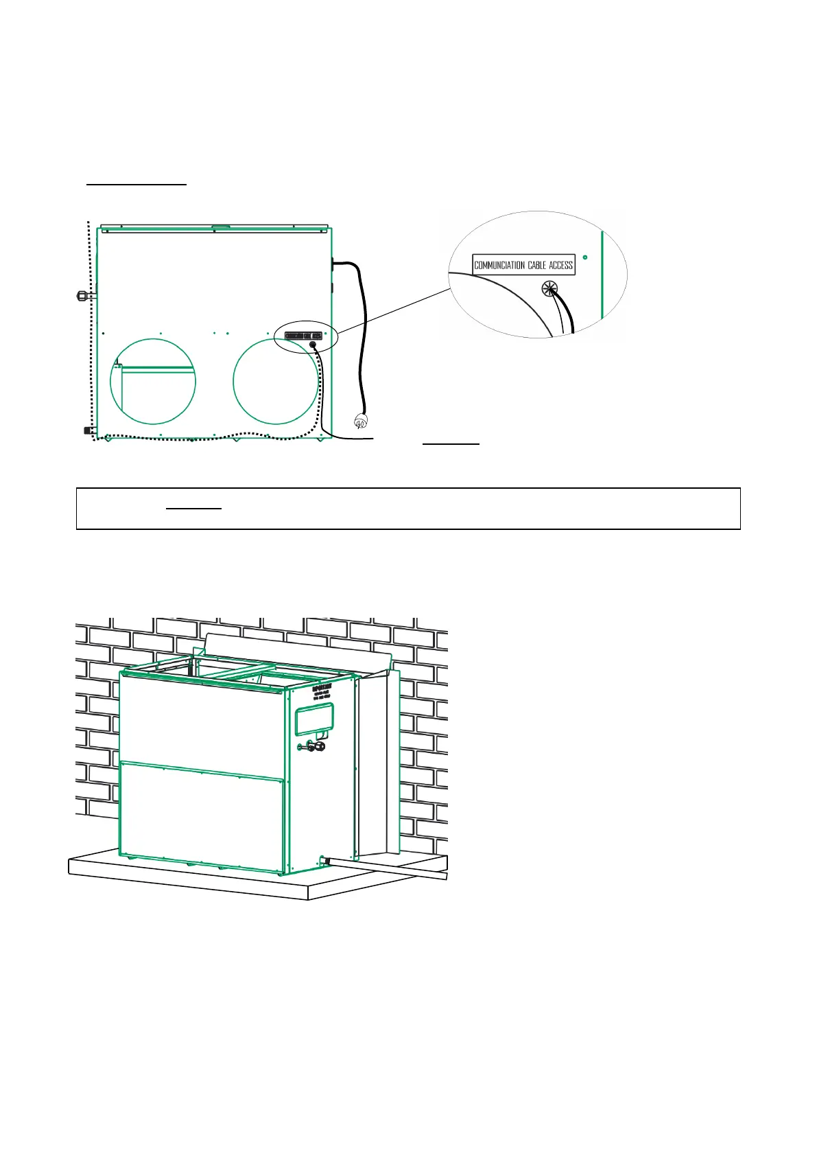
This cable is field supplied and shall access the Icebox through a grommet located beneath the flashings
on the return air side, refer to Diagram 13. Run the cables under the flashing; do not drill any holes in the
flashing for cable access.
Diagram 13: Wiring into the Icebox
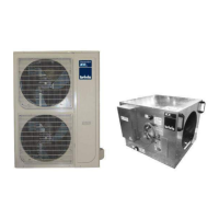
Diagram 14: Flashing & Condensate installation
7. Run a bead of silicone on the
flashing faces that will mate with
the house.
8.
Push Icebox into position up
against the building wall.
9. Install condensate drain.
Note: 2-core shielded communication cable shall be installed from the Icebox unit (Terminals S1 & S2) to
the condenser unit. The shield of the cable shall be earthed at the condenser end only, refer Diagram 15.
2-Core Shielded Communication Cable to CDU
BX5 - Heater PCB (refer Diagram 19)
BX3 - Programmable thermostat (refer Diagram 20)