Specifications subject to change without notice. © 2013 Brivis Climate Systems Pty Ltd
18
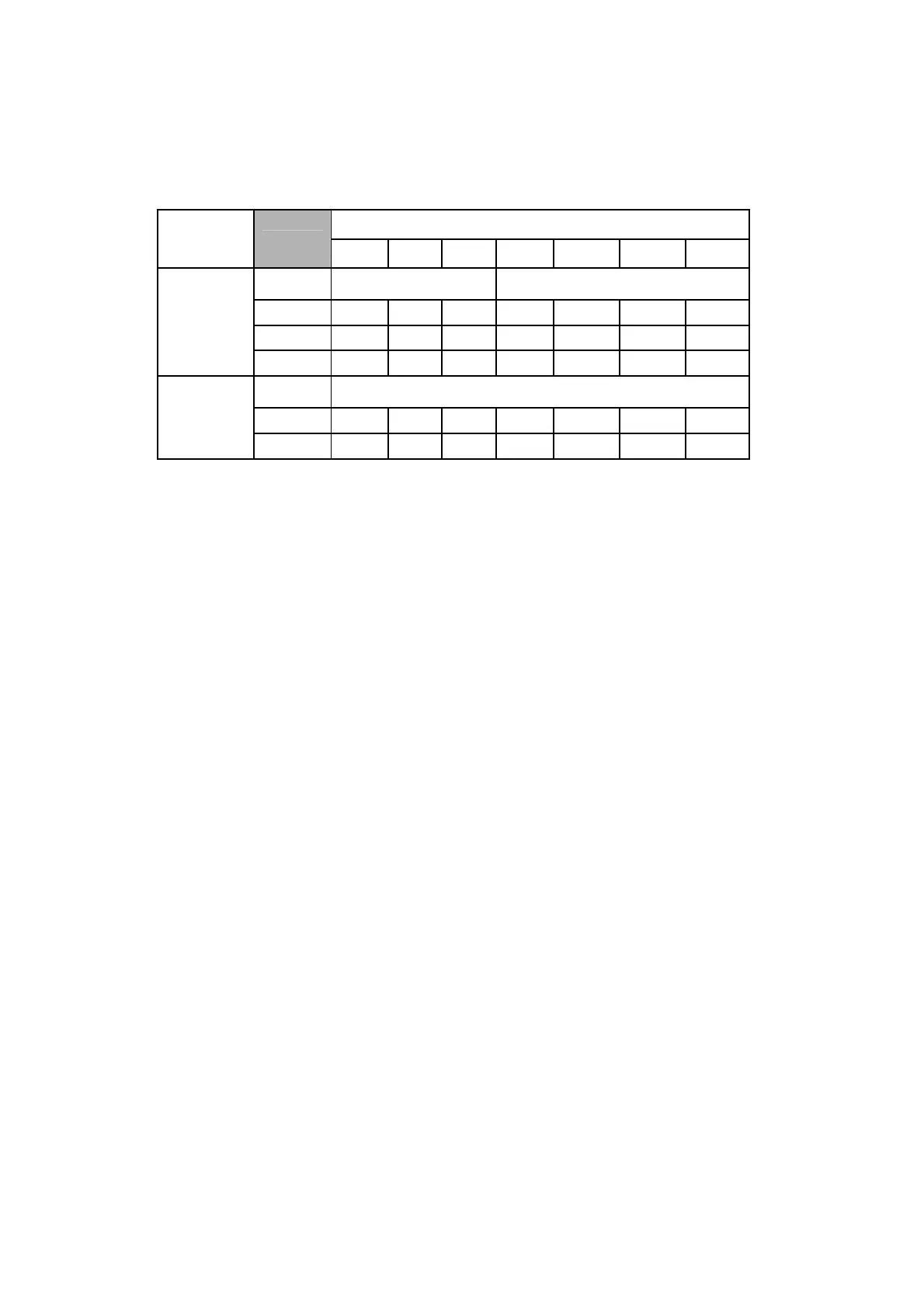
6.4 Correction Factors: vapour line sizing vs. cooling capacity
The total equivalent length of the interconnecting refrigeration lines will affect the cooling capacity of the system. Table 3
shows the percentage change in cooling capacity versus the equivalent pipe lengths for different suction line sizes, using
the recommended liquid line sizes.
Equivalent Pipe Length (m)
Model
5 7.5 10 15 20 25 30
Suction
line (mm)
9.52mm Liquid Line 12.7mm Liquid Line
28.6 2.0% 1.7% 1.4% 0.9% 0.4% -0.06% -0.50%
22.2 0.9% 0.0% -0.8% -2.5% -4.2% -5.9% -7.7%
DO-SC18Z9
19.1 -1.6% -3.7% -5.6% -9.9% -14.2% -18.5% -23.0%
Suction
line (mm)
12.7mm Liquid Line
28.6 0.43% 0.0% -0.4% -1.2% -2.0% -2.8% -3.6%
DO-SC22Z9
22.2 -1.4% -2.8% -4.2% -6.8% -9.6% -12.4% -15.2%
Table 3 – Cooling Capacity Correction Factors
6.5 Pipe-work connection
• Locate the suction & liquid pipe service valves in the compressor compartment by removing the service access
panel
• Check that the service valves are tightly closed (Service Ball valves have been provided for suction and liquid
lines)
• Wrap each valve in turn with a wet cloth prior to sweating off its associated blanking plate
• Braze the interconnecting liquid and suction pipes from the indoor unit
• Pressurise the indoor unit & pipe-work again with dry nitrogen and check for any brazed joint leaks. Repair as
necessary but ensure the system is not under pressure prior to brazing
• With the indoor unit pressure again released, evacuate to a vacuum pressure of 100 microns minimum
• Disconnect the vacuum pump whilst retaining the system vacuum
• Open the liquid line valve fully first, and then the suction line valve
6.6 Charging the system
Once all electrical connections are correctly made, the unit is ready to be commissioned. Start the system in cool mode and
allow it to stabilise before checking liquid line sub-cooling and compressor suction superheat. Refer to Start Up and
Commissioning procedures (Section 7).
• The system is pre-charged with R410a refrigerant for 15m actual pipe length
• For lengths greater than 15m, additional charge is required. This is done by starting the unit and using it to draw
refrigerant (liquid only) through the compressor suction pipe Schrader valve, located in the compressor
compartment. Refer to Section 6.2.
• For pipe lengths shorter than 7m it will be necessary to remove some refrigerant (45g per metre for 9.5mm liquid
line). This can be done through the liquid pipe valve located in the outdoor unit compressor compartment. Any
excess refrigerant shall be reclaimed, by suitably qualified personnel.
The correct measurement and assessment of superheat and sub-cooling values should be the only measures used
to confirm correct system charge.
• Superheat should be between 4 and 9K
• Sub-cooling should be between 2 and 8K
• Discharge gas temperature should not exceed 130°C in any circumstances
• Do not overcharge.