Specifications subject to change without notice. © 2013 Brivis Climate Systems Pty Ltd
8
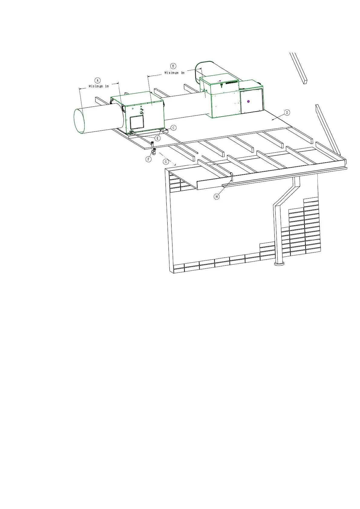
A. Ensure 1m minimum, or preferably 2½ times
the duct diameter, STRAIGHT duct length
before any take-offs occur
B. Ensure 1m minimum STRAIGHT duct
between the Gas Ducted Heater and ICE
coil unit
C. Safety Drain Tray (Field supplied),
independently drained
D. Working Platform (field supplied)
E. Unit Supports (field supplied)
F. P Trap Assembly on primary condensate
drain – fit as close as possible to unit
G. Condensate drain pipe to be pitched down
and to be terminated in an approved manner
as specified by local codes
H. Terminate the Safety Drain Tray in a position
so as not to cause a nuisance, but where the
home owner can see if water is dripping.
Instruct owner to contact Installer or Brivis if
Safety Drain Tray outlet drips water
3.0 TYPICAL INSTALLATION
Fig. 6 - Typical Indoor Installation
4.0 INDOOR COIL INSTALLATION
• Indoor coils are supplied with a nitrogen holding charge ranging from 400kPa to 700kPa
• Connect a suitable pressure gauge to the indoor coil valve to ensure the internal pressure is at least 400kPa
• If the measured pressure is less than 400kPa, check and if necessary repair any leaks found before proceeding
• Remove the nitrogen holding charge by connecting a charging line with valve depressor
• Sweat off the liquid & suction pipe blanking plates and proceed to pipe up in line with the good piping practices
• Some heaters may require a transition to modify its starting collar (pop) size to suit the inlet pop size of the ICE
indoor coil. DO NOT REDUCE POP SIZES ON INDOOR COIL or HEATER
• Ensure minimum specified air quantity requirement passes through the ICE cooling coil at all times
• Ductwork and fittings must be sized to handle the total cooling airflow through the system on either whole home or
zoned basis
• If the Brivis Heater requires a remote thermistor installed in the supply air ductwork, position it in the supply air
starting collar (discharge pop) of the cooling coil (see Section 4.5)
4.1 Location
• Choose a location that is suitable for refrigeration piping and condensate drainage
• Allow adequate provision is made for service access
• Indoor coil unit is not weatherproof and should be installed so that there is no chance of direct sunlight, water or
moisture coming into contact with the outer casing
• Where the unit is installed in the roof or ceiling space ensure the building structure is capable of supporting the
unit’s weight – do not suspend unit from support handles
• Brivis ICE indoor units shall be installed only downstream and at least 1m distance from heater’s main supply air
outlet and always before the first duct branch-take-off fitting
• Never put the Indoor coil in the Return Air part of the duct system, this may result in condensation forming in the
Heater, causing corrosion and damage to vital components