53-1004408-11 Installation Guide
Brocade
®
G610 Switch Hardware Installation Guide
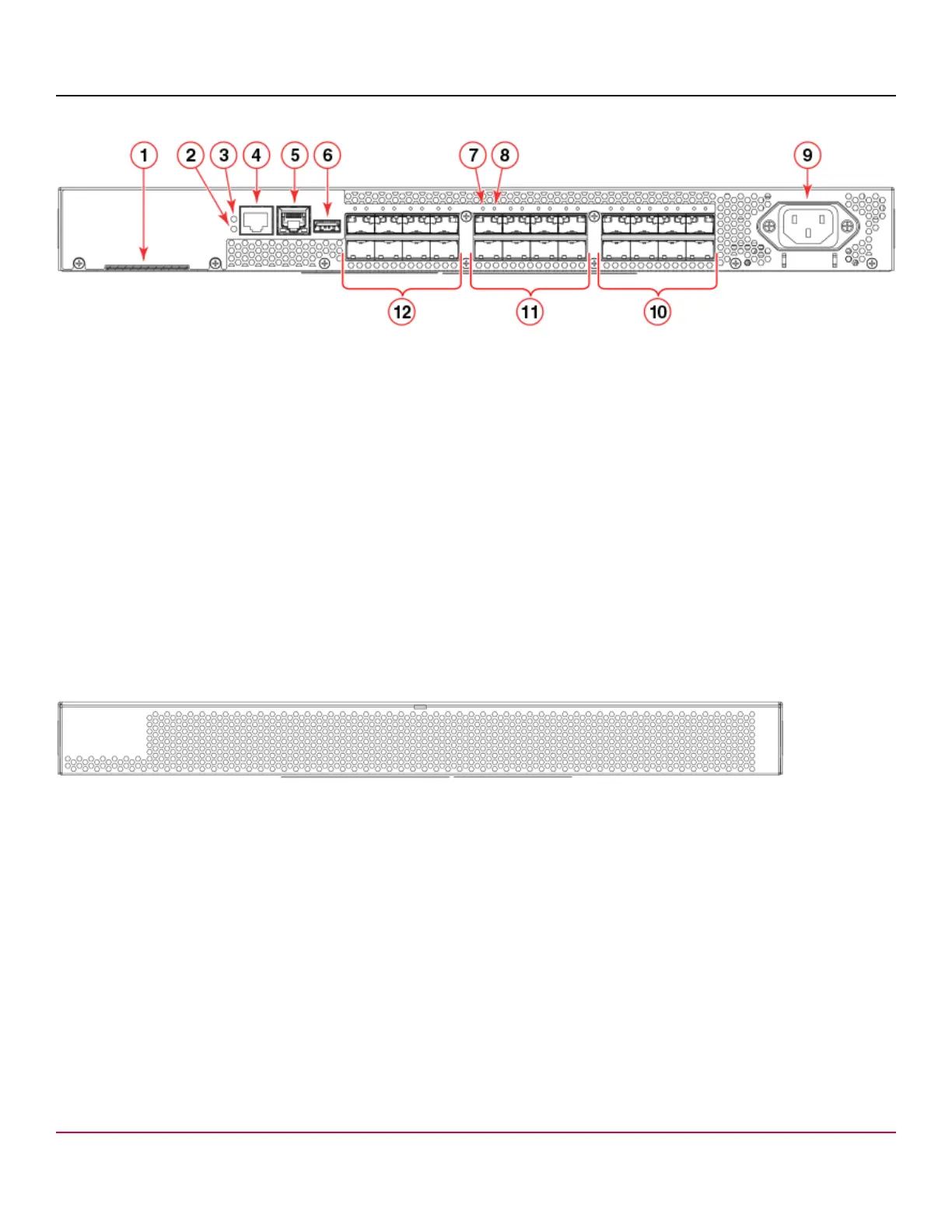
Figure 1: Port-Side View
1. Switch ID Pull-Out Tab
2. System Status LED
3. System Power LED
4. System RS-232 Console Port (RJ-45)
5. Ethernet Port with Two Ethernet Status LEDs
6. USB Port
7. SFP+ FC Port 8 (Upper) Status LED
8. SFP+ FC Port 12 (Lower) Status LED
9. AC Power Receptacle
10. Trunk Port Group 2 (SFP+ FC Ports 16-23)
11. Trunk Port Group 1 (SFP+ FC Ports 8-15)
12. Trunk Port Group 0 (SFP+ FC Ports 0-7)
Nonport-Side View
The nonport side of the device is used solely for air flow.
Figure 2: Nonport-Side View
Device Management Options
You can use the management functions built into the device to monitor the fabric topology, port status, physical status, and
other information to help you analyze switch performance and to accelerate system debugging. The device automatically
performs a power-on self-test (POST) each time it is turned on. A RASlog message is generated for any detected startup
errors.
You can manage the device using any of the management options listed in the following table.
53-1004408-11
10