Do you have a question about the Broadcom G610 and is the answer not in the manual?
Overview of the hardware installation guide's content and purpose.
Lists supported Brocade G610 FC Switch hardware and software.
Explains symbols and severity of safety notices used in the document.
Details the features and capabilities of the Brocade G610 Switch.
Explains the capacity-based Dynamic-POD license method for port activation.
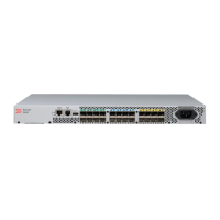
Illustrates the port-side view of the Brocade G610 Fibre Channel Switch.
Describes the nonport side of the device, used for airflow.
Lists management tools and their out-of-band support and reference documents.
General safety guidelines and warnings for product usage and installation.
Guidelines to prevent damage from electrostatic discharge during installation.
Safety guidelines related to electrical power supply and handling.
Safety practices for lifting and mounting the device in a rack.
Warnings and precautions related to Class 1 lasers in fiber-optic interfaces.
Specifies electrical, thermal, and rack requirements for device installation.
Provides a high-level overview of the basic installation process.
Details tasks for mounting and basic system configuration.
Lists the items included in the device's shipping carton.
Describes different ways to install the device (stand-alone, various rack kits).
Specific safety warnings and precautions related to mounting the device.
Steps for installing the device as a stand-alone unit on a flat surface.
Guide for installing the 1U/2U Mid-Mount Rack Kit for Two-Post Racks.
Instructions for attaching front brackets to the device for rack mounting.
Steps for securing the device into the rack using the mounting brackets.
Instructions for attaching rear brackets to the rack posts.
Instructions for attaching rear brackets to the device chassis.
Guide for installing the 1U/2U Fixed-Mount Rack Kit for Four-Post Racks.
Guide for installing the 1U/2U Nonport-Side Fixed-Mount Rack Kit.
Instructions for attaching rear brackets to the rack posts.
Lists necessary items for initial setup and verification of the device.
Steps to connect and provide power to the Brocade G610 Switch.
Procedures for establishing a serial connection to the device for initial configuration.
Steps to set the IP address for the switch using DHCP or static configuration.
Procedures for setting the system date, time, and time zone.
Guide to changing the chassis and switch names for identification.
Steps to establish an Ethernet connection to the device.
Procedures for setting the switch's domain ID for fabric operation.
Methods to check if the device is functioning correctly after setup.
Instructions for backing up the device configuration to prevent data loss.
Steps to safely power down the Brocade G610 Switch.
Lists time and items needed for transceiver and cable installation.
Safety warnings for handling transceivers and fiber optic cables.
Guidelines for cleaning fiber-optic connectors to ensure proper connection.
Recommendations for organizing and managing fiber-optic cables.
Step-by-step guide for inserting an SFP+ transceiver into the switch ports.
Procedures for removing and installing SFP+ transceivers.
Commands to verify the correct operation of installed transceivers.
Explains how to interpret the status indicated by the LEDs on the switch's port side.
Details the status and interpretation of the system power LED.
Explains the status and interpretation of the system status LED.
Describes the function and status of the management port LEDs.
Explains the status patterns for the Fibre Channel (FC) SFP+ port LEDs.
How to interpret the results of the power-on self-test (POST) based on LED activity.
Describes the tasks performed by the switch after POST is complete.
Information on running diagnostic tests for troubleshooting hardware and firmware.
Lists enclosure, power, cooling, and architecture details of the switch.
Details specifications for the switch's Fibre Channel ports.
Specifications for serial console, Ethernet, and USB ports.
Describes the system, Ethernet, and FC port LEDs.
Provides weight and physical dimension specifications for the device.
Lists operational and non-operational environmental conditions for the switch.
Details the input voltage, frequency, current, and inrush current of the power supply.
Specifies port numbers, media type, and configuration for FC ports.
Details the pinout and signal assignments for the serial console port.
BSMI warning statement for Class A product in Taiwan.
Compliance statement for Canadian Interference-Causing Equipment Regulations.
CE mark compliance for European Council directives and standards.
China CCC warning statements for product usage and altitude.
China RoHS compliance statement for hazardous substances.
FCC warning for Class A computing device operated in commercial environments.
Machine noise information regulation for Germany.
EMC registration statement for Class A device in Korea.
VCCI statement regarding Class A product and potential radio disturbance.
Lists electromagnetic compatibility compliance standards for the device.
Lists safety compliance standards for the device.
Lists environmental compliance regulations for the device.
Explains danger statements indicating lethal or extremely hazardous conditions.
General warnings about procedures and potential hazards for service personnel.
Warnings related to electrical hazards, including ESD precautions.
Warnings about securing the rack to prevent instability or falling.
Warnings and precautions related to Class 1 lasers in fiber-optic interfaces.
General warnings about modifying the device or operating conditions.
Cautions regarding slot filler panels and power supply insertion.
Cautions for DC power supply circuits, wiring, and grounding.