EasyManua.ls Logo

Broadcom Brocade G720 - User Manual

Broadcom Brocade G720
86 pages
Print Icon
To Next Page IconTo Next Page
Loading...
Brocade
®
G720 Switch Hardware Installation Guide
Installation Guide
18 December 2020
G720-Install-IG101
18 December 2020
Broadcom

Table of Contents

Question and Answer IconNeed help?

Do you have a question about the Broadcom Brocade G720 and is the answer not in the manual?

Broadcom Brocade G720 Specifications

General IconGeneral
BrandBroadcom
ModelBrocade G720
CategorySwitch
LanguageEnglish

Summary

Brocade G720 Switch Hardware Installation Guide

Introduction

About This Document

Provides an overview of the installation guide, safety requirements, and configuration steps for the Brocade G720 Switch.

Supported Hardware and Software

Lists the power supply and fan assemblies and rack mount kits supported by the Brocade G720 Switch.

Contacting Technical Support for Your Brocade Product

Details methods for contacting Brocade technical support for product assistance and issue resolution.

Device Overview

Hardware Features

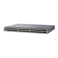
Describes the key hardware components and capabilities of the Brocade G720 Switch.

Device Management Options

Lists and describes various tools and methods for managing and configuring the Brocade G720 Switch.

Preparing for Installation

Safety Precautions

Outlines essential safety measures to be taken before and during the installation process.

Facility Requirements

Details the necessary electrical, thermal, and rack space requirements for installing the device.

Mounting the Device

Mounting Options

Describes the different ways the Brocade G720 Switch can be installed, including stand-alone and rack-mounted.

Precautions Specific to Mounting

Highlights critical safety warnings and precautions related to physically mounting the device.

Stand-alone Installation

Provides step-by-step instructions for installing the device as a stand-alone unit on a flat surface.

Copyright Statement

Stand-alone Installation

Installing the Universal Four-Post Rack Kit (XBR-R000296)

Parts List

Details the components included in the universal four-post rack kit.

Flush-Front Mounting

Attaching the Front Brackets

Steps to attach the front brackets to the Brocade G720 Switch device.

Installing the Device in the Rack

Steps to place and secure the device with attached brackets into the rack.

Flush-Rear (Recessed) Mounting

Attaching the Rear Brackets to the Rack Posts

Steps to secure the rear brackets to the uprights of the rack.

Installing the Universal Two-Post Rack Kit (XBR-R000294)

Parts List

Details the components included in the universal two-post rack kit.

Attaching the Rear Brackets to the Device

Mid-Mounting

Attaching the Front Brackets to the Rack

Steps to attach front brackets to the rack posts.

Initial Setup and Verification

Providing Power to the Device

Step-by-step instructions for connecting and powering on the Brocade G720 Switch.

Establishing a First-Time Serial Connection

Configuring the IP Address

Setting a Static IP Address

Provides steps to manually configure a static IP address for the switch.

Setting the Date and Time

Setting the Time Zone

Customizing the Chassis Name and Switch Name

Establishing an Ethernet Connection

Verifying Correct Operation

Backing Up the Configuration

Powering Down the Device

Installing Transceivers and Cables

Precautions Specific to Transceivers and Cables

Safety warnings regarding the use of fiber-optic interfaces and lasers.

Installing an SFP+ Transceiver

Replacing an SFP+ Transceiver

Verifying the Operation of New Transceivers

Monitoring the Device

Interpreting Port-Side LEDs

Explains the status indicated by the LEDs on the port side of the Brocade G720 Switch.

System Power LED

Details the patterns and meaning of the system power status LED.

System Status LED

Explains the different states of the system status LED and their implications.

FC Port Status LEDs

Explains the status indicated by the LEDs for the Fibre Channel ports.

Interpreting Nonport-Side LEDs

Interpreting POST Results

Running Diagnostic Tests

Power Supply and Fan Assembly

Precautions Specific to the Power Supply and Fan Assemblies

Critical safety warnings and precautions for handling power supplies and fan assemblies.

Identifying the Airflow Direction

How to identify intake and exhaust airflow directions for power supply and fan assemblies.

Power Supply and Fan Assembly Fault Indicators

Methods for determining the status of power supply and fan assemblies using LEDs and commands.

Recording Critical Information about the Power Supply and Fan Assembly

Removing a Power Supply and Fan Assembly

Inserting a New Power Supply and Fan Assembly

Verifying the Operation of the Power Supply and Fan Assemblies

Brocade G720 Switch Technical Specifications

System Specifications

Details enclosure, power, cooling, and system architecture specifications.

Fibre Channel Ports

Technical specifications for the 56 SFP+ Fibre Channel ports.

LEDs

System power LED

Describes the green system power status LED on the port side.

System status LED

Describes the bicolor system status LED on the port side.

FC port status LEDs

Explains the status indicated by the LEDs for the Fibre Channel ports.

Power supply and fan assembly status LEDs

Describes the status LEDs for the power supply and fan assemblies.

Weight and Physical Dimensions

Environmental Requirements

Power Supply Specifications (Per PSU)

Regulatory Statements

BSMI Statement (Taiwan)

Taiwan's Bureau of Standards, Metrology and Inspection (BSMI) warning statement for Class A products.

Canadian Requirements

Compliance statement for Canadian Interference-Causing Equipment Regulations.

CE Statement

Statement regarding CE mark compliance with European Council directives and standards.

China CCC Statement

China ROHS

FCC Warning (U.S. Only)

KCC Statement (Republic of Korea)

Taiwan ROHS Certification

VCCI Statement

Regulatory Compliance

Regulatory Compliance (EMC)

Lists EMC compliance standards and directives applicable to the device.

Cautions and Danger Notices

General Cautions

Specific caution statements regarding device modifications, airflow, and slot fillers.

Electrical Cautions

Danger Notices

General Dangers

General danger statements about qualified personnel and fan tray safety.

Electrical Dangers

Dangers related to ESD wrist straps and electrical shock.

Battery safety

Risks associated with batteries used for RTC/NVRAM backup and their disposal.

Dangers Related to Equipment Weight

Laser Dangers

Revision History

Related product manuals