Brocade FastIron GS and FastIron GS-STK Hardware Installation Guide 73
53-1001783-01
Device specifications
6
DRAFT: BROCADE CONFIDENTIAL
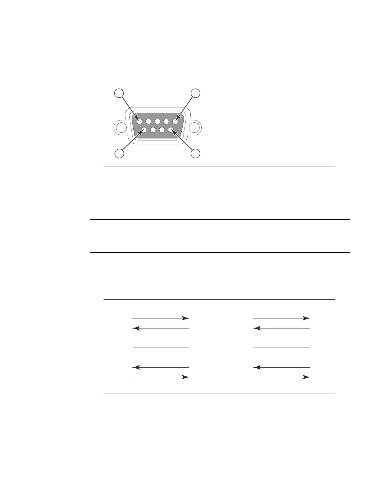
FIGURE 48 Serial Port Pin and Signalling Details
Most PC serial ports require a cable with a female DB-9 connector. However, terminal connections
will vary, requiring a cable with either a DB-9 or DB-25 connector, male or female.
Serial cable options between the FastIron GS or GS-STK and a PC or terminal are shown in
Figure 49.
As indicated in Figure 48 and Figure 49, some of the wires should not be connected. If you do
connect the wires that are labeled “Reserved”, you might get unexpected results with some
terminals.
FIGURE 49 Console Port Pin Assignments Showing Cable Connection Options to a Terminal or PC
10/100/1000 Gigabit port pinouts
Table 50 lists the pin assignment and signalling for 10/100/1000 ports.
5
96
1
Pin Assignment
DB-9 male
Pin Number
Switch Signal
1 Reserved
2 TXD (output)
3 RXD (input)
4 Reserved
5 GND
6 Reserved
7 CTS (input)
8 RTS (output)
9 Reserved
1
2
3
4
5
6
7
8
9
1
2
3
4
5
6
7
8
9
8
3
2
20
7
6
4
5
22
1
2
3
4
5
6
7
8
9
DB-9 to DB-9
Female Switch
Terminal or PC
Reserved
Reserved
Reserved
Reserved
DB-9 to DB-25
Female Switch
Terminal or PC
Reserved
Reserved
Reserved
Reserved
 Loading...


