4 Brocade ICX 6430-C Compact Switch Hardware Installation Guide
53-1002817-02
Port, system, and power status LEDs
1
1GbE RJ45 ports
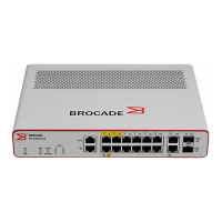
An ICX t6430-C device provides 12 RJ45 ports that reside on Slot 1 of the device. The 12 RJ45
ports operate at 10 Mbps or 100 Mbps half or full duplex, or at 1000 Mbps full duplex. Because all
ports support automatic MDI or MDI-X operation, you can use straight-through cables for all
network connections to PCs or servers, or to other devices or hubs. In addition, it is ideal (and
preferred) to use straight-through cables for switch-to-switch connections.
Each port supports auto-negotiation, so the optimum transmission mode (half or full duplex), and
the data rate (10, 100, or 1000 Mbps) can be selected automatically. If a device connected to one
of these ports does not support auto-negotiation, the communication mode of the port can be
configured manually.
100/1GbE uplink ports
An ICX 6430-C device provides 4 independent 100Mbps/1GbE uplink ports.
100/1GbE RJ45 ports C1 and C2, residing on slot 2 of the device, can be used as uplink ports or
additional network connections.
Additionally, an ICX 6430-C device contains two 100Mbps/1GbE small form factor pluggable (SFP)
ports (ports F1 and F2). These ports reside on slot 3 of the switch and can be used as uplink ports.
In future releases they can be used for stacking, though the stacking functionality is not available
in release 08.0.00. The SFP ports support 100Mbps/1GbE port speeds.
For information about supported SFP transceivers, refer to the following Brocade website:
http://www.brocade.com/downloads/documents/data_sheets/product_data_sheets/Optics_
DS.pdf
Port, system, and power status LEDs
An ICX 6430-C device include LEDs that indicate the status of device components:
• “Port status LEDs”
• “System status LEDs” (including power status LEDs)
• “Network connection status LEDs”
Port status LEDs
Figure 4 shows the location of the port status LEDs on the ICX 6430-C12 model.

 Loading...