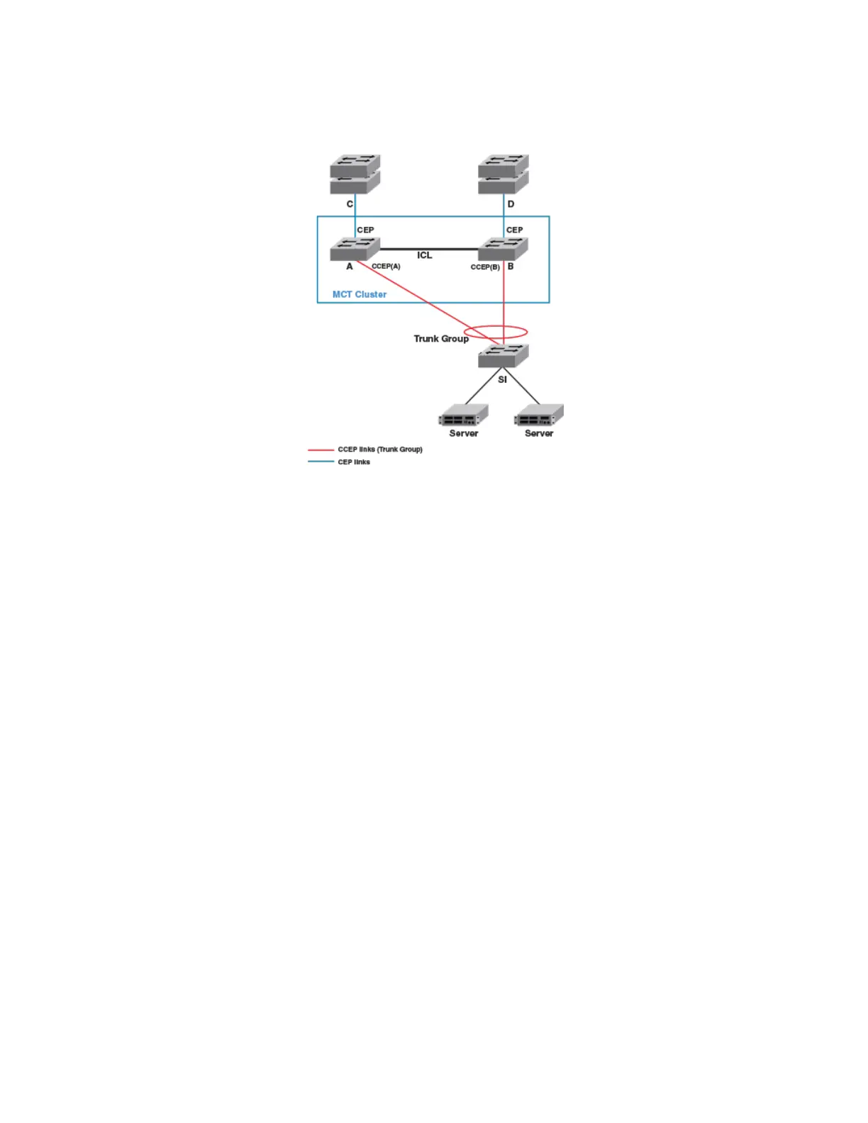
FIGURE 39 Conguration for Layer 3 unicast
Layer 3 trac forwarding towards MCT clients
Trac destined to the MCT clients follows normal IP routing. By default, the best route should not involve the ICL link. Only when the
local CCEP is down is trac rerouted to pass over the ICL.
Layer 3 trac forwarding from MCT clients
For Layer 3 forwarding to work on MCT devices, a dynamic trunk must be congured on the MCT client. Routes should be statically
congured or dynamically learned on the MCT cluster devices.
The client routes the trac towards its next hop, which can be either one of the MCT devices. If ECMP is deployed on the client, each
MCT device can be a possible next hop. In such a deployment, the trac can be load balanced at a Layer 3 level over the next two hops.
Because a LAG is deployed at the client, this trac is further subjected to load balancing at the Layer 2 level over the physical ports in
the LAG. Thus, the trac being sent out with the next hop as one of the MCT devices can either reach it directly or through the cluster
peer (where it gets Layer 2 switched towards the intended next hop).
Therefore, almost 50 percent of trac being forwarded from MCT clients (and as much as 100 percent trac in the worst case) can pass
through the ICL. This fact should be considered when designing the ICL capacity in the network.
VRRP or VRRP-E over an MCT-enabled network
To interface a Layer 2 MCT deployment with a Layer 3 network and add redundancy at the Layer 3 level, MCT can be
congured with
Virtual Router Redundancy Protocol (VRRP). The standard VRRP mode is master-backup, and all trac is forwarded through the master.
In VRRP-E server virtualization, multiple VRRP standby devices are supported, and each device can be congured to route to an
upstream Layer 3 network. This provides ecient deployment for both Layer 2 and Layer 3 networks.
The MCT device acting as a backup router will Layer 2 switch all packets destined to VRRP/ VRRP-E virtual MAC address to the VRRP/
VRRP-E master router for routing. The VRRP/VRRP-E backup learns the virtual MAC address while processing the VRRP hello
message from the VRRP master. Both data trac and VRRP/VRRP-E control trac travel through the ICL unless the short-path
forwarding feature is enabled (VRRP-E only).
Layer 3 behavior with MCT
FastIron Ethernet Switch Layer 3 Routing
53-1003627-04 573
 Loading...