E0608
Brookeld Engineering Laboratories, Inc. Page 9 Manual No. M00-151-I0614
II. GETTING STARTED
II.1 Operation
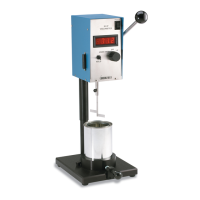
MOTOR
ON/OFF/PAUSE
POWER SUPPLY
RECEPTACLE
SPEED KNOB
(rpm)
CLUTCH LEVER
Note: See Appendix D for
image of Explosion Proof
Viscometer.
GUARD LEG
CLAMP
1. Be sure the plug of the power supply
is securely plugged into your power
source.
2. Plug the metal jack of the power
supply into the circular receptacle
on the back of the Viscometer.
3. The black, rubber baton switch on
the viscometer controls the motor
and has three positions:
UP: Off - turns the motor off and
stops the dial from turning
MIDDLE: On - causes the dial to
rotate at the selected speed
DOWN: Pause (or motor stop)
- causes the dial to pause when
rotating
4. LV Viscometers use a set of four spindles and a narrow guard leg; RV Viscome ters use a set
of six spindles and a wider guard leg; HA and HB Viscometers use a set of six spindles and no
guard leg.
5. Speeds (rpm) are changed by turning the black knob on the top of the viscometer (to the left or
right) to the desired speed.
6. The clutch lever, when depressed, raises the dial against the red pointer and "holds" the Viscometer
reading. Releasing the clutch lowers the dial and frees the pointer.
Top View Front View