Do you have a question about the Brother DCP-7080D and is the answer not in the manual?
Provides a comparative table for model functions, specifications, and features.
Details network capabilities like wired and wireless node types for various models.
Lists machine and part life, MTBF, MTTR, and periodical maintenance parts.
Specifies toner cartridge and drum unit life expectancy and shelf life.
Details paper input, media weight, and size supported by the ADF.
Lists fax modem speed, transmission speed, and ITU-T group.
Details copy speed, first copy out time, and resolution specifications.
Lists optical and interpolated resolution, and scanning speed for monochrome and color.
Explains the meaning of WARNING, CAUTION, IMPORTANT, Note, and Memo conventions used in the manual.
Explains troubleshooting purpose and outlines essential precautions for service personnel.
Lists critical warnings and precautions to avoid secondary problems during maintenance.
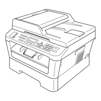
Provides a visual flow chart to guide the disassembly and reassembly process.
Details necessary actions and preparations after replacing the main PCB unit.
Explains how to enter maintenance mode for service personnel and end-user accessible functions.
Presents the overall wiring diagram illustrating electrical component connections and layout.
States that there are no specific parts designated for periodic replacement.
Explains how to interpret the serial number format and its components on the machine label.
Details the step-by-step procedure for installing the maintenance printer driver on Windows XP.
| Brand | Brother |
|---|---|
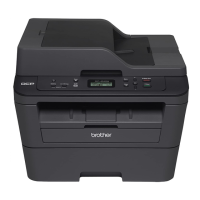
| Model | DCP-7080D |
| Category | All in One Printer |
| Language | English |