Home
Brother
All in One Printer
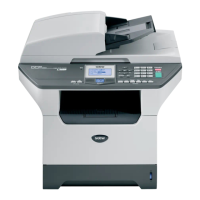
DPC-8060
Brother DPC-8060 User Manual
4
of 1
of 1 rating
492 pages
Give review
Manual
Specs
To Next Page
To Next Page
Loading...
Confident
ial
FA
CSIMILE EQUIPMENT
SERVICE MANUAL
MODELS: MFC-8460N/8860DN/8870DW
DCP-8060/8065DN
2
Table of Contents
Table of Contents
5
Default Chapter
1
Service Manual
1
Parts Names & Functions
3
Specifications
3
Theory of Operation
3
Safety Precautions
14
To Use the Machine Safely
14
Choosing a Location
16
Chapter 1 Parts Names & Functions
17
Equipment Outline
19
Front View
19
Rear View
19
Control Panel
20
Components
25
Chapter 2 Specifications
26
General
28
General Specifications
28
Media Specifications
29
Paper Handling
29
Paper Specifications
29
Pcl5E/Epson/Ibm Emulation
32
Printable Area
32
PCLXL, PS (BR-Script 3)
35
Print Speeds with Various Settings
36
Toner Cartridge Weight Information
37
Specifications List
38
Chapter 3 Theory of Operation
63
Chapter 3 Theory of Operation
64
Default Chapter
65
Overview
65
Mechanical Components
66
Scanner Mechanism
67
Overview of Gear
73
Paper Supply
74
Paper Transfer
74
Drum Unit
76
Paper Registration
76
Developing
77
Fixing Stage
78
Paper Eject
79
Duplex Printing (for the Models with the DX Only)
80
LT Tray
81
Paper Feeding from the MP Tray
81
Toner Cartridge
82
Toner Life End Mode
82
New Toner Detection Mechanism
84
Counter Reset During Indication of "Toner Life End
85
Print Process
86
Charging
86
Exposure Stage
86
Transfer
87
Sensors
88
Components
89
Control Electronics
89
Transferring Received Fax Data
91
Chapter 4 Transfer of Data Left in the Machine to be Sent for Repair
92
Transferring Received Fax Data
92
Disassembly/Reassembly (Lt-5300)
98
Chapter 5 Disassembly/Reassembly
100
Safety Precautions
100
Tightening Torque
101
Harness Routing
103
Interlock SW ASSY
104
Register Solenoid Assy
105
Mp Solenoid Assy
106
T1 Solenoid Assy
106
Laser Unit
107
Relay Front Pcb Assy
107
Fan Motor 60 Unit
108
Fan Motor 60 Unit Lv
108
Toner Led Pcb Unit Assy
109
Ps Pcb Unit
110
Adf Unit
111
Panel Unit
115
Speaker Assy
115
Fuser Unit
116
How to Access the Object Component
120
Preparation
120
Disassembly Flowchart
121
AC Cord
122
Drum/Toner ASSY
122
DX Feed ASSY (for the Models with the DX Only)
123
Paper Tray
123
Back Cover
126
Outer Chute ASSY
127
Access Cover/Side Cover L
129
ADF Unit
130
Hinge Base R
131
Hinge Arm R
132
Hinge ASSY L
132
ADF Cover ASSY
133
ADF Side Cover F
133
ADF Side Cover R
134
ADF Chute ASSY
135
SB Chute ASSY (for the Models with the DX Only SX Chute (for the Models with out the DX Only)
137
Exit Chute Cover ASSY
137
Earth Spring
138
PF Roller Holder ASSY
139
LF Roller 1 ASSY
140
SB Roller ASSY (for the Models with the DX Only)
141
ADF Motor
143
PF Solenoid ASSY (for the Models with the DX Only)
144
ADF Relay PCB
145
Paper Feed Chute ASSY
146
ADF Film/Spring Plate ADF Front a Assy/Separation Rubber/Rubber Holder Separation Spring
149
LF Roller 2 ASSY
150
Exit Roller ASSY
151
LF Roller 3 ASSY
152
LF Roller 4 ASSY
153
Document Hold/Document Hold Spring
155
Upper Main Chute Assy/Lower Main Chute ASSY
155
Actuator R/Photo Interrupter
157
Flap B
158
Actuator Sb/Photo Interrupter (for the Models with the DX Only)
158
Document Ejection Tray
159
Document Cover Sensor
160
Eject Roller B4
160
Presser Roller
161
Panel Cover ASSY
162
Scanner Unit ASSY
163
Top Cover ASSY
164
Lock Lever B/Lock Lever ASSY
164
CCD Module
165
FFC Cable ASSY
167
Scanner Motor FB
168
Pulley ASSY
169
Photo Interrupter
169
Panel Unit
170
Panel PCB ASSY
171
Printed Rubber Key
172
LCD Cover/Backlight Module/Lcd
173
NCU PCB ASSY (for the Models with the NCU Only)
174
Speaker ASSY
176
Driver PCB
177
Fuser Unit
178
Tray MP ASSY
180
MP Tray Cover Assy/Process Cover ASSY
181
Main PCB
184
Gear Plate Calking ASSY Al/Develop Joint/Main Motor ASSY al
185
Main Shield Plate ASSY
187
Relay Rear PCB Assy/Connector
189
Relay Front PCB ASSY
191
MP Solenoid ASSY
192
Drive Release Link
193
T1 Solenoid ASSY
194
Toner Sensor PCB
194
Register Solenoid ASSY
195
Ejector Solenoid ASSY (for the Models with the DX Only)
195
Interlock SW ASSY
196
New Toner Actuator
196
Gear 17/20/23
197
Side Cover R
199
Thermistor ASSY
199
Joint Cover ASSY
200
Filter
201
Laser Unit
202
PS PCB Unit
203
High-Voltage PS PCB ASSY
206
Toner LED PCB Unit ASSY
208
Fan Motor 60 Unit
209
Fan Motor 60 Unit LV
209
Frame L
210
Frame R
210
MP Unit
211
Regist Actuator Rear/Regist Actuator Spring
216
Regist Actuator Front/Regist Actuator Spring
218
Roller Holder ASSY
219
PE Actuator/Edge Actuator/Edge Actuator Spring
220
Wireless PCB (PCB T60H929.00 ASSY 02) (for the Model with the Wireless Only)
223
Disassembly/Reassembly (Lt-5300)
224
Paper Tray
224
LT Front Cover ASSY
227
LT Rear Cover
228
LT Side Cover L
228
LT Side Cover R
229
Lt Pcb Assy
230
Connector: 54702-1219
231
Connector: 55533-1219
231
Gear 24 LT
232
Collar 6
233
LT Solenoid ASSY
237
Roller Holder ASSY
238
Edge Actuator Spring
239
LT Sensor PCB ASSY
241
Lubrication
243
Chapter 6 Adjustments and Updating of Settings, Required after Parts Replacement
245
Default Chapter
245
If You Replace the Main Pcb
245
If You Replace the Main Pcb
246
Acquire of White Level Data and Set the CCD Scanner Area (Function Code 55)
246
Check the Control Panel PCB for Normal Operation (Function Code 13)
246
Customize the EEPROM on the Main PCB (Function Code 74)
246
Initialize the EEPROM on the Main PCB (Function Code 01)
246
Load Update Programs/Data
246
Make a Sensor Operation Check (Function Code 32)
246
Setting the Serial Number
246
Switch Back to Standby
247
If You Replace the Document Scanner Unit
247
Acquire of White Level Data and Set the CCD Scanner Area (Function Code 55)
247
If You Replace the Drum Unit
247
Periodical Replacement Parts
248
Fuser Unit and Laser Unit
249
Procedures to Replace Periodical Replacement Parts
249
Paper Feeding Kit for Tray 1, 2
277
Paper Feeding Kit for MP Tray
284
Chapter 7 Cleaning
292
CHAPTER 8 Maintenance Mode
292
Chapter 8 Maintenance Mode
293
Default Chapter
294
Entry into the Maintenance Mode
294
List of Maintenance-Mode Functions
295
User-Access to the Maintenance Mode
296
Detailed Description of Maintenance-Mode Functions
297
EEPROM Parameter Initialization (Function Code 01/91)
297
Printout of Scanning Compensation Data (Function Code 05)
298
ADF Performance Test (Function Code 08)
302
Placement of CCD Unit in Position for Transportation (Function Code 06)
302
Test Pattern 1 (Function Code 09)
303
Firmware Switch Setting (Function Code 10)
304
Firmware Switch Setting and Printout
304
Printout of Firmware Switch Data (Function Code 11)
306
Operation Check of LCD (Function Code 12)
307
Operational Check of Control Panel PCB (Function Code 13)
308
Sensor Operational Check (Function Code 32)
309
Received Data Transfer Function (Function Code 53) (Not Applicable to DCP-8060/8065DN.)
311
Fine Adjustment of Scan Start/End Positions (Function Code 54)
313
Acquisition of White Level Data and CCD Scanner Area Setting (Function Code 55)
315
EEPROM Customizing (Function Code 74)
316
Paper Feeding and Ejecting Test (Function Code 67)
316
Display of the Equipment's Log Information (Function Code 80)
317
Machine Error Code Indication (Function Code 82)
319
Output of Transmission Log to the Telephone Line (Function Code 87) (Not Applicable to DCP-8060/8065DN.)
319
Cancellation of the Memory Security Mode (Not Applicable to with out the NCU Models and the Japanese Model.)
320
Counter Reset after Replacing the Fuser Unit, Laser Unit and Paper Feed Kit (Function Code 88)
320
Other Service Function
321
Resetting the Developing Bias Voltage Counter
321
Chapter 9 Error Indication and Troubleshooting
322
Troubleshooting
322
Chapter 9 Error Indication and Troubleshooting
323
Error Indication
324
Equipment Errors
324
Error Messages Appearing on the LCD
324
Communications Errors
335
Troubleshooting
339
Introduction
339
Precautions
339
Checking Prior to Troubleshooting
339
Troubleshooting Based on Problem Type
340
Paper Feeding Problems
340
Software Setting Problems
342
Malfunction
345
Image Defects
351
Incorrect Printout
371
Network Problem
373
Troubleshooting of the Control Panel
380
Troubleshooting of Fax Functions
382
Operating Procedure
398
Other manuals for Brother DPC-8060
Servise Manual
495 pages
Quick Setup Guide
37 pages
4
Based on 1 rating
Ask a question
Give review
Questions and Answers:
Need help?
Do you have a question about the Brother DPC-8060 and is the answer not in the manual?
Ask a question
Brother DPC-8060 Specifications
General
Copying
Yes
Maximum copy resolution
600 x 600 DPI
Scanning
Yes
Functions
Copying, Printing, Scanning
Scan to
Email, OCR
Connectivity
USB
Related product manuals
Brother DCP-130C
103 pages
Brother DCP-195C
2 pages
Brother DCP-T310
539 pages
Brother DCP-145C
108 pages
Brother DCP-J100
91 pages
Brother DCP-J125
220 pages
Brother DCP-7020
79 pages
Brother DCP-1511
96 pages
Brother DCP-135C
98 pages
Brother DCP 8060
171 pages
Brother DCP-7057
239 pages
Brother DCP-115C
112 pages