Do you have a question about the Brother P-touch QL-700 and is the answer not in the manual?
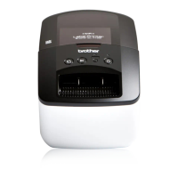
Details on the physical dimensions, weight, buttons, display, printing mechanism, tape, cutter, and PC interface.
Information on character generator and power supply specifications for the Brother QL-700.
Explanation of the internal mechanisms, including print, tape feed, and cutter systems.
Overview of the control electronics components and their functions, including PCBs and motors.
Essential safety guidelines to follow during disassembly and reassembly procedures.
Specific torque values for screws used in various assemblies of the printer.
Identifies specific points within the printer that require lubrication and the type of grease to use.
Step-by-step instructions for disassembling the printer, from cover removal to component extraction.
Step-by-step instructions for reassembling the printer after servicing or repair.
Important precautions to prevent secondary problems during troubleshooting.
Verification and adjustment procedures after completing a repair.
Explanation of status LED indicators and their meanings in different situations.
List of error messages displayed by the printer and recommended advice.
Diagnostic flowcharts for common printing and operational issues.
Purpose and steps for using the VR Adjustment Tool for sensor calibration.
Prerequisites and setup for using the Serviceman Software Tool for inspection.
Detailed steps for running the Serviceman Software Tool for inspection and diagnostics.
Specific procedures for performing various inspection items using the software tool.
Procedure for checking the operation of the P-touch Editor Lite software.
| Print Technology | Direct Thermal |
|---|---|
| Maximum Tape Width | 62 mm |
| Print Resolution | 300 dpi |
| Connectivity | USB |
| Cutter | Automatic |
| Operating Systems Supported | Windows, Mac |
| Label Types | Die-cut labels, continuous tape |
| Compatible Label Width | 62 mm |
| Power Source | AC adapter |