MAINTENANCE PROCEDURES
not required, it is recommended that
an authorized Lynx dealer performs
spark plugs inspection or replacement.
Engine Stopper
( E-TEC models)
Engine Stopper Adjustment
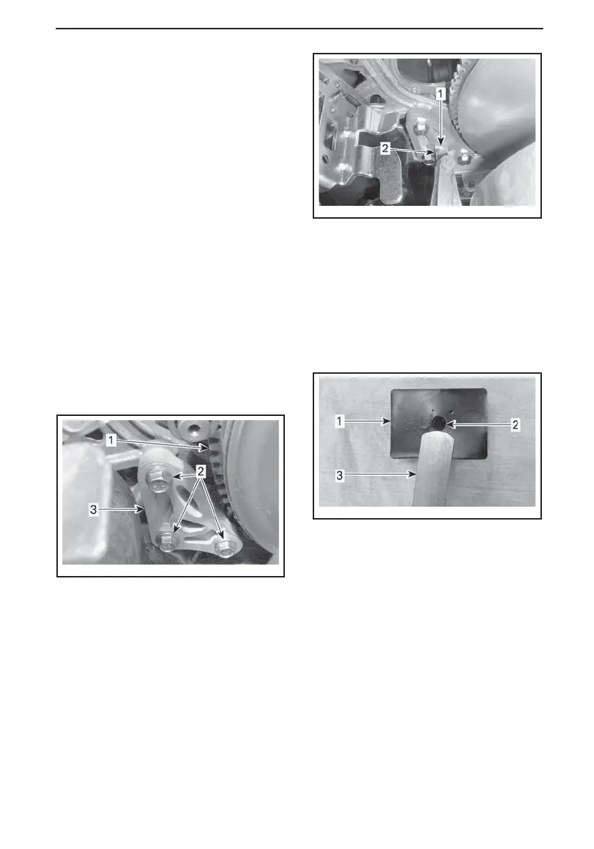
The engine stopper is located on the
LH front engine support, in front of the
drive pulley.
1. Remove tether cord cap from en-
gine cut-off switch.
2. Remove the LH lower side panel, re-
fer to
CONTROLS, INSTRUMENTS
AND EQUIPMENT
.
3. Remove drive belt guard, refer to
DRIVE BELT GUARD REMOVAL
.
4. Loosen the three screws retaining
the engine stopper to the engine
support just enough to allow a verti-
cal play (1/2 to one turn).
mmo2010-009-007_a
1. Drive pulley
2. Engine stopper screws
3. Engine stopper
5. Insert a 0.5 mm (.02 in) feeler gauge
in the engine stopper opening (see
illustration).
mmo2010-009-001_a
1. Opening
2. Feeler gauge
6. Place feeler gauge between engine
stopper and rubber stop block (on
engine).
NOTE: Do not insert the feeler gauge
too deep, as it will pass over the bump
at the surface of the rubber stop block
and alter adjustment. See illustration.
mmo2010-009-002_a
1. Rubber stop block
2. Bump
3. Feeler gauge
7. Tighten screws to specification, fol-
lowing the illustrated sequence.
Take care not to pinch the feeler
gauge.
______________
101